
| 307-01A Automatic Transmission - Vehicles With: 6-Speed Automatic Transmission - 6F50 | 2013 - 2014 MKZ |
| Overhaul | Procedure revision date: 02/25/2013 |
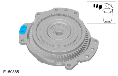
NOTICE: The torque converter is heavy. Be careful not to drop it or damage will result.
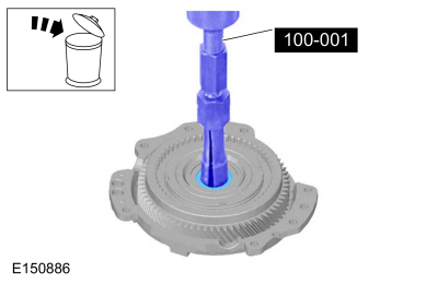
NOTICE: Only thread the bolts 6 to 8 turns or do not exceed 12 mm (0.472 in) into the torque converter. If the bolts are threaded too far, damage to the torque converter clutch surface can occur causing torque converter failure.
NOTE:
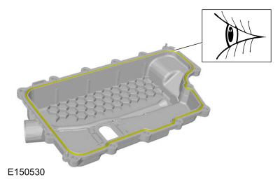
NOTICE: Do not use water-based cleaners or mineral spirits to clean or flush the torque converter or transmission damage will occur. Use only clean transmission fluid designated for the transmission and torque converter being serviced.
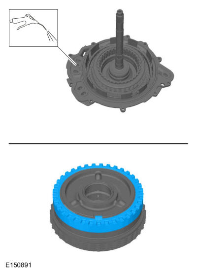
NOTE: Note the location of the studbolts for assembly.
NOTICE: Handle the solenoid body with care or damage to the solenoid body may occur.
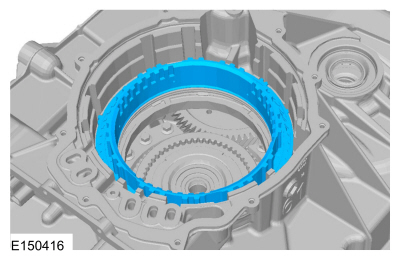
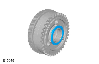
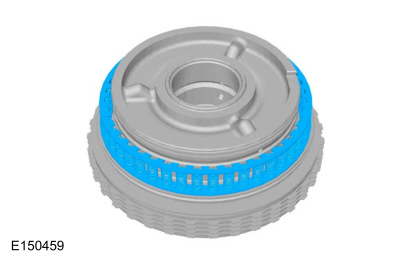
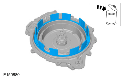
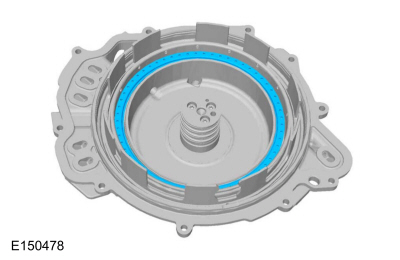
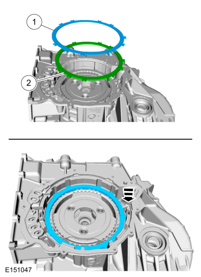
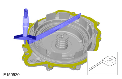
NOTE: The location of the tab on the bottom pressure plate is aligned with the gap for the low One-Way Clutch (OWC) snap ring.
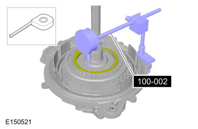
NOTE: Note the orientation of the snap ring for assembly. The snap ring gap must fit around the tab of the low/reverse clutch pressure plate.
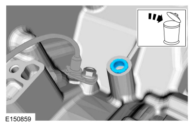
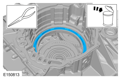
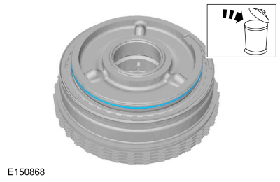
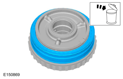
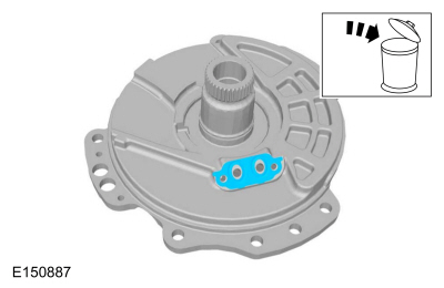
NOTICE: Do not clean in water or with water-based solvents. Damage to the component may occur.
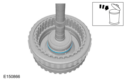
NOTE: The low One-Way Clutch (OWC) cannot be disassembled.
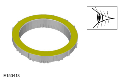
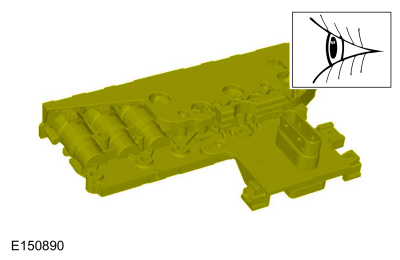
Check for cracks and damaged splines. The internal splined section should rotate counterclockwise and lock when rotated clockwise.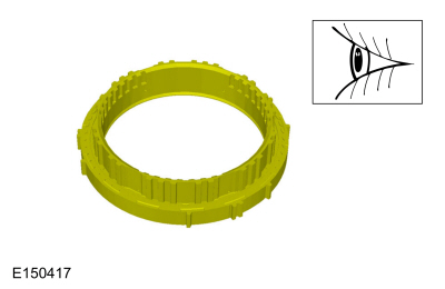
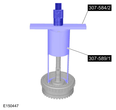
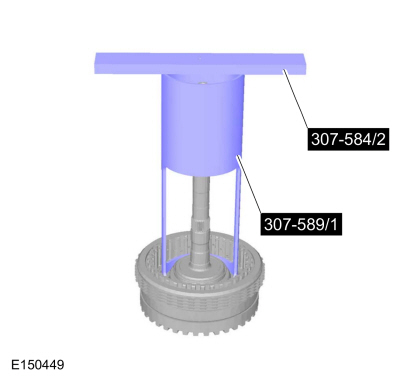
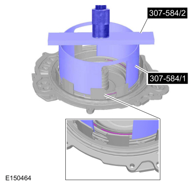
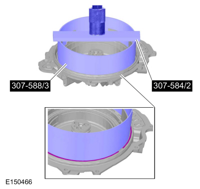
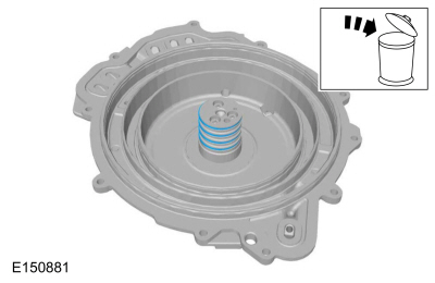
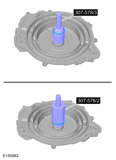
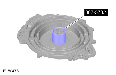
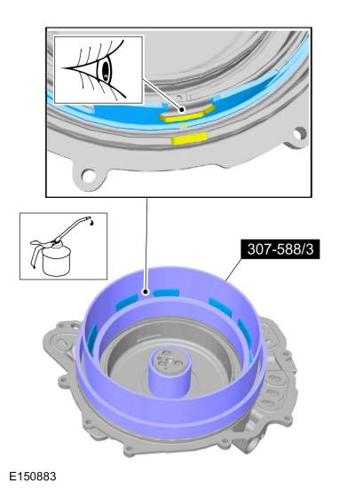
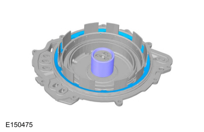
NOTE: Install the Compressor, Forward/Intermediate Spring 307-584 (307-584/1 and 307-584/2) with the stepped end of the cylinder facing upward when compressing the forward clutch piston return spring.
Compress the forward clutch piston return spring.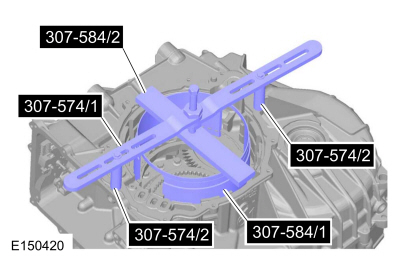
NOTE: The Compressor, Forward/Intermediate Spring 307-584 (307-584/1 and 307-584/2) and the Compressor, Forward Clutch Spring 307-574 (307-574/1 and 307-574/2) are not shown for clarity.
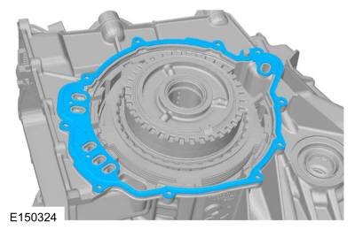
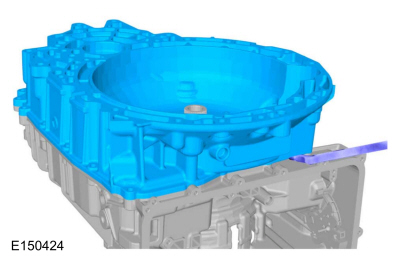
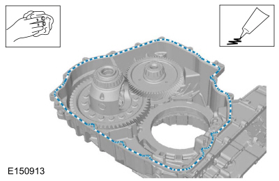
NOTICE: Carefully pry on the transmission torque converter housing and the case to separate the torque converter housing from the case. Do not pry up on the silicone sealant mating surfaces, damage to the mating surfaces may occur. Carefully lift the torque converter housing off the dowel pins.
NOTICE: If a differential bearing is damaged, a new bearing and bearing cup must be installed on both sides of the differential or excessive noise or transmission failure can occur.
NOTICE: If a transfer shaft bearing is damaged, a new bearing and bearing cup must be installed on both sides of the transfer shaft or excessive noise or transmission failure can occur.
NOTICE: If the transfer shaft bearing cup is damaged, a new bearing and bearing cup must be installed on both sides of the transfer shaft or excessive noise or transmission failure can occur.
If the transmission case side transfer shaft bearing cup is damaged, install a new bearing cup.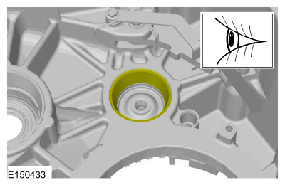
NOTICE: If the differential bearing cup is damaged, a new bearing and bearing cup must be installed on both sides of the differential or excessive noise or transmission failure can occur.
If the transmission case side differential bearing cup is damaged, install a new bearing cup.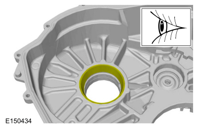
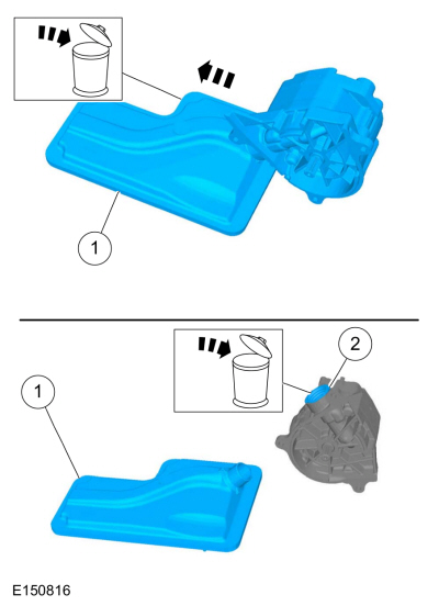
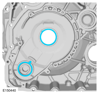
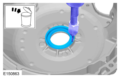
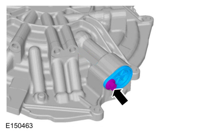
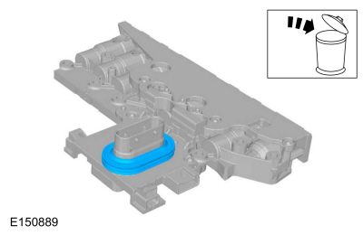
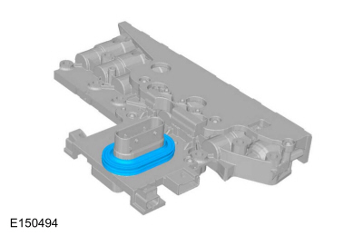
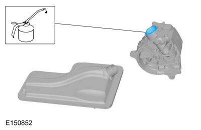
NOTE: Note the orientation of the fluid filter to the fluid pump.
NOTICE: If the transfer shaft bearing cup is damaged, a new bearing and bearing cup must be installed on both sides of the transfer shaft or excessive noise or transmission failure can occur.
If the torque converter housing side transfer shaft bearing cup is damaged, install a new bearing cup.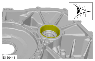
NOTE: FWD vehicles
NOTICE: If the differential bearing cup is damaged, a new bearing and bearing cup must be installed on both sides of the differential or excessive noise or transmission failure can occur.
If the torque converter housing side differential bearing cup is damaged, install a new bearing cup.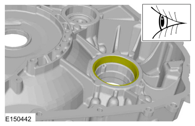

NOTICE: Only compress the direct clutch piston return spring far enough to take the tension from the direct clutch cylinder off the snap ring. If the piston is compressed too far, the piston alignment tab may be broken off.
NOTICE: Only compress the direct clutch piston return spring far enough to install the direct clutch cylinder snap ring. If the piston is compressed too far, the piston alignment tab may be broken off.
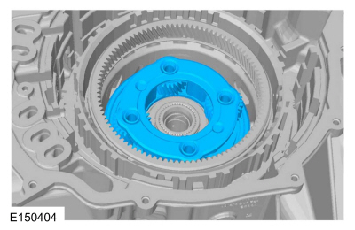
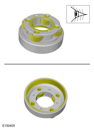
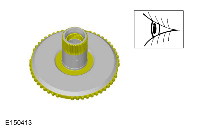
NOTE: Align the tab on the direct clutch cylinder with the slot on the overdrive/direct clutch hub and shaft assembly.

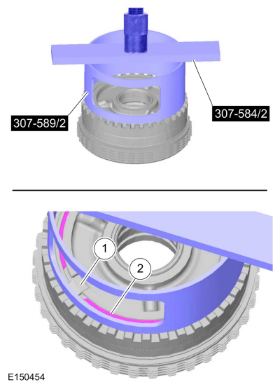
NOTE: Push the overdrive clutch piston in the cylinder by hand using the Compressor, Overdrive Clutch, Balance Piston and Direct Clutch 307-589/1.
Special Tool(s) : 307-589 Overdrive clutch and balance piston service set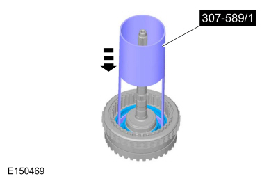
NOTE: Install the overdrive clutch piston return spring so that the holes are facing upward.
NOTE: Install the low/reverse piston return spring with the tabs facing down.
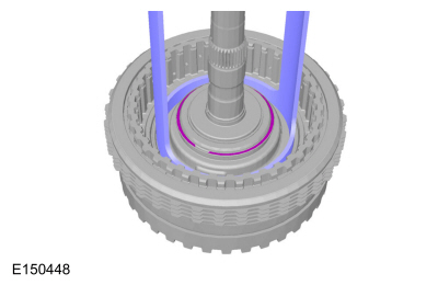
NOTE: Make sure the snap ring is fully seated in the groove before releasing the pressure on the return spring.
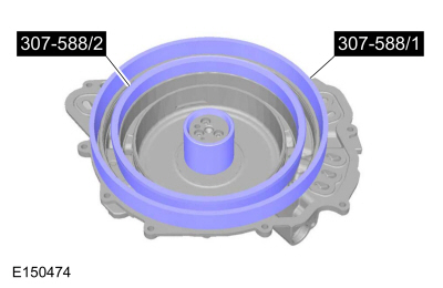
Special Tool(s) : 307-584 2-6 Spring Compressor , 307-588 Reverse clutch piston and retaining ring set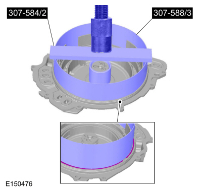
NOTE: Make sure the snap ring is fully seated in the groove before releasing the pressure on the return spring.
Special Tool(s) : 307-584 2-6 Spring Compressor
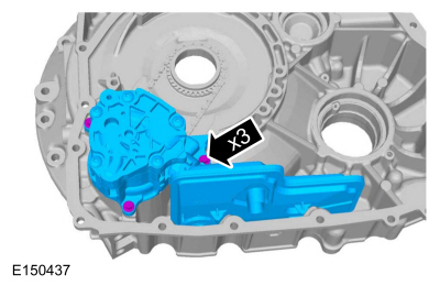
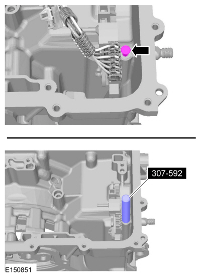
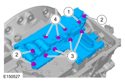
NOTE: Note the location of the Torx® head and the hex head bolts for assembly.
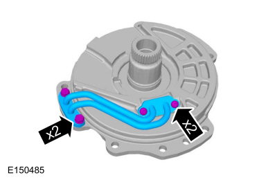

NOTE: Install the Torx® and the hex bolts in the correct locations as noted during disassembly.
Hand tighten.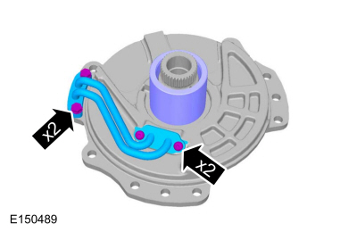
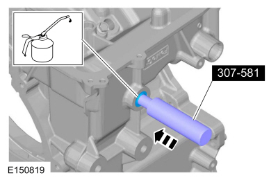
NOTICE: The solenoid body should be handled with care or damage to the solenoid body may occur.
NOTICE: Do not handle the solenoid body in the internal wiring harness frame area or by the screens of the solenoid body filter or damage to the solenoid body may occur.
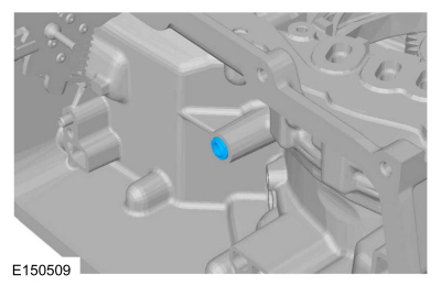
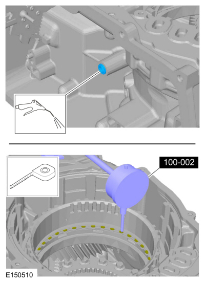
NOTICE: Use care not to break the alignment tabs when installing the solenoid body filter. Damage to the transmission will occur if the solenoid body is not correctly aligned.
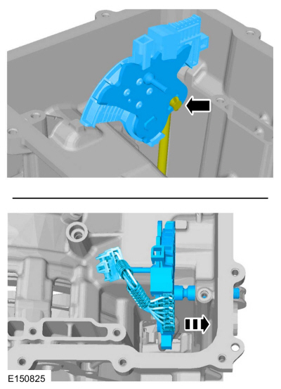
Pull straight up from the alignment tabs.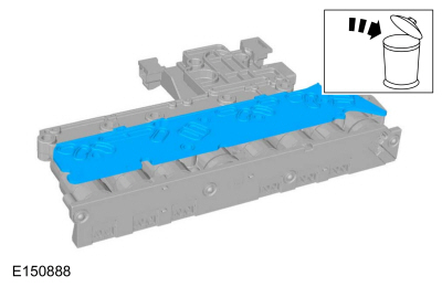
NOTICE: Do not handle the solenoid body in the internal wiring harness frame area or by the screens of the solenoid body filter or damage to the solenoid body may occur.
NOTICE: Use care not to break the alignment tabs when installing the solenoid body filter. Damage to the transmission will occur if the solenoid body is not correctly aligned.
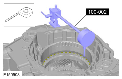
NOTICE: Make sure that the filter passage areas are clean of foreign material before installing the filter. Damage to the transmission will occur if the filter passages are not clean.
Push filter straight down onto the alignment tabs.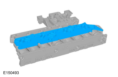
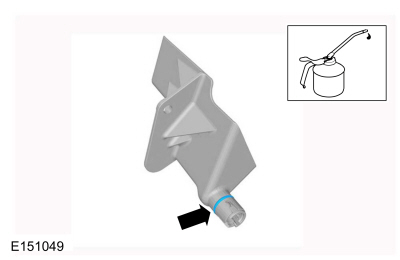
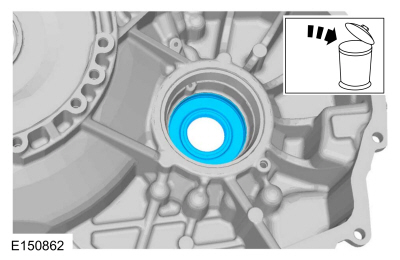
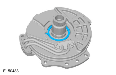
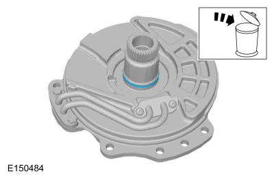
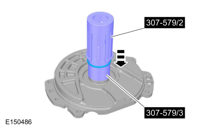
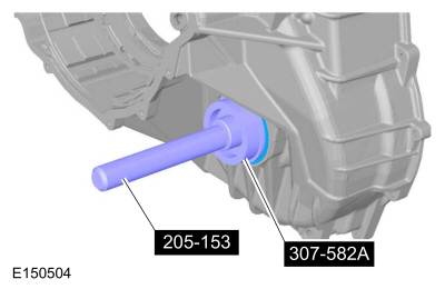
NOTICE: Support the torque converter housing using blocks of wood, or damage to the torque converter housing may occur.
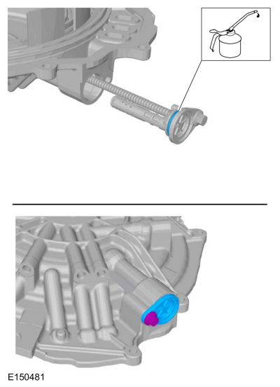
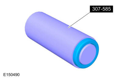
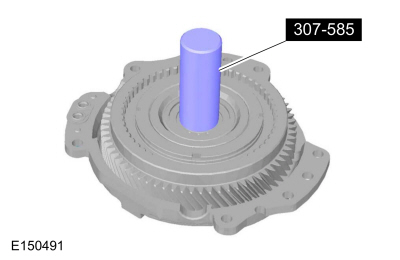
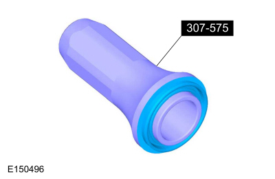
Special Tool(s) : 307-575 Converter Seal Installer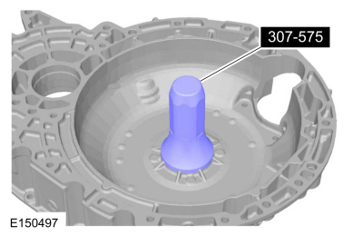
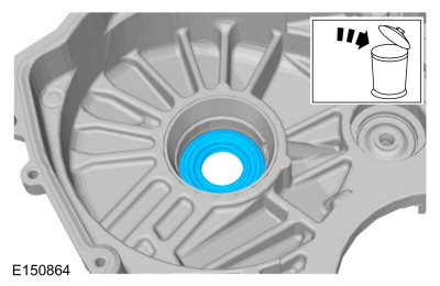
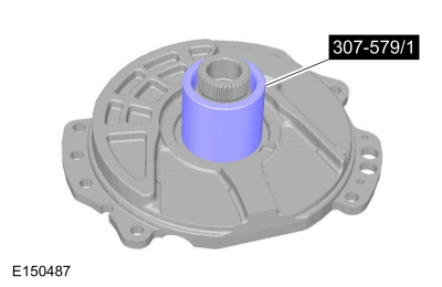
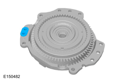
NOTE: FWD vehicles
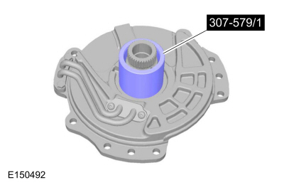
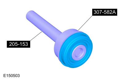
Special Tool(s) : 205-153 (T80T-4000-W) Handle , 307-582A Cover Axle Seal Installer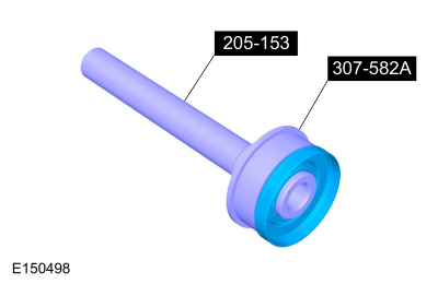
NOTICE: Support the torque converter housing using blocks of wood, or damage to the torque converter housing may occur.
Special Tool(s) : 205-153 (T80T-4000-W) Handle , 307-582A Cover Axle Seal Installer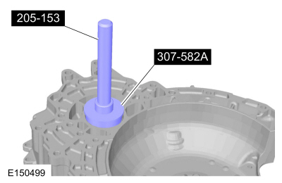
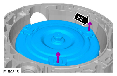
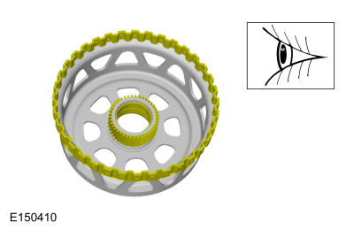
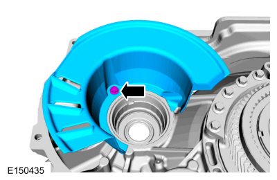
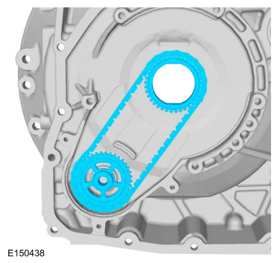
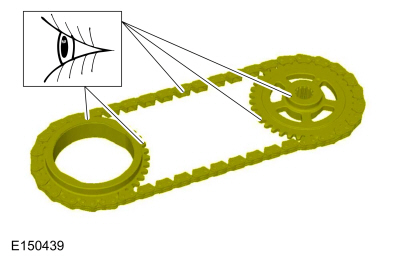
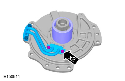
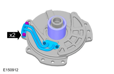
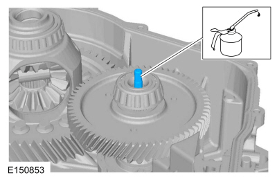
NOTE: The dot on the pump sprocket is installed facing upward.
NOTE: Install the filter in the correct orientation as noted in removal.
NOTE: Be sure that the pump drive chain is correctly engaged on both sprockets.
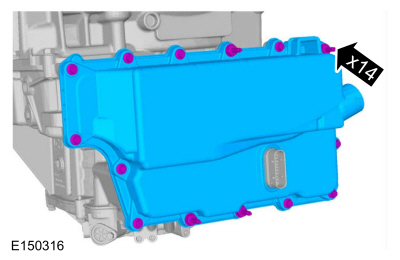
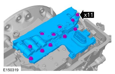
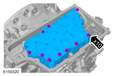
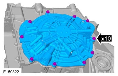
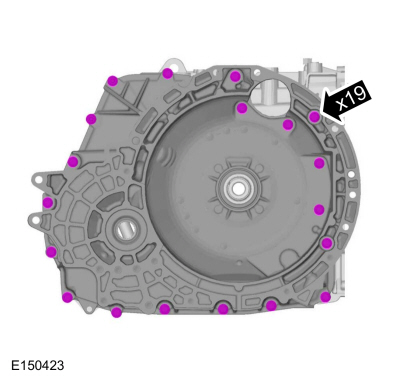
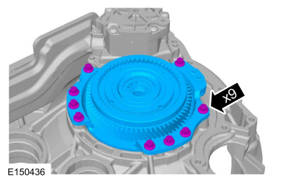
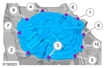
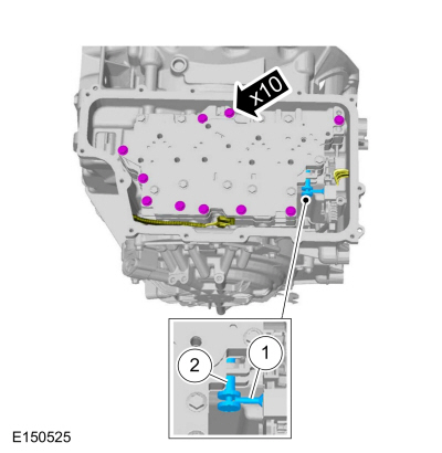
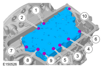
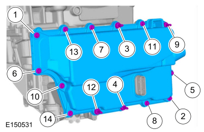
Tighten in the sequence shown.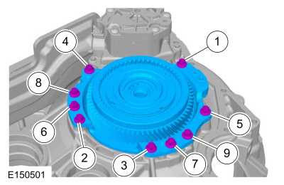
NOTE: Hand tighten the bolts only.
NOTE: The studbolts are 1 and 16 in the tightening sequence.
Torque : 24 Nm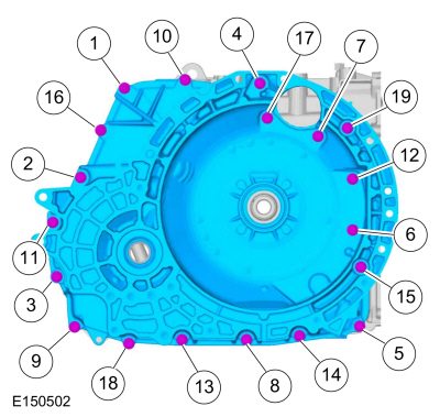
NOTE: Install the Compressor, Forward/Intermediate Spring 307-584/1 with the stepped end of the cylinder facing downward when pushing the forward clutch piston into the bore.
Special Tool(s) : 307-584 2-6 Spring Compressor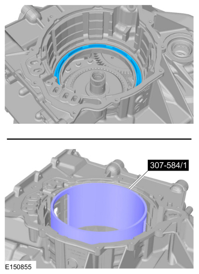
NOTE: Install the Compressor, Forward/Intermediate Spring with the stepped end of the cylinder facing upward when compressing the forward clutch piston return spring.
NOTE: Install the Forward/Overdrive Spring Compressor with the stepped end of the cylinder facing upward when compressing the forward clutch piston return spring.
NOTE: Before compressing the forward clutch piston return spring, make sure the spring is centered.
Special Tool(s) : 307-574 Forward Clutch Spring Compressor , 307-584 2-6 Spring CompressorNOTE: The Compressor, Forward Clutch Spring and the Compressor, Forward/Intermediate Spring not shown for clarity.
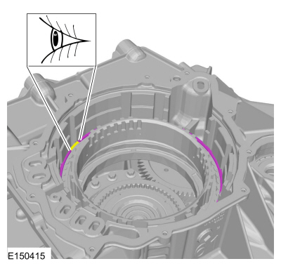
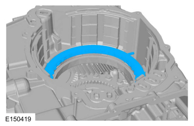
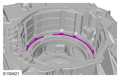
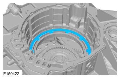
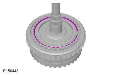
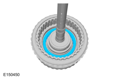
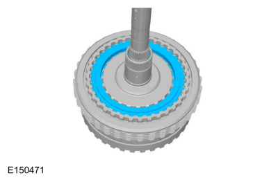
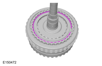
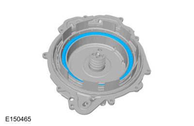
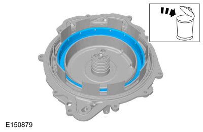
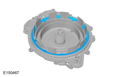
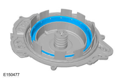
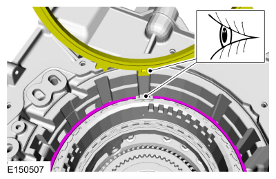
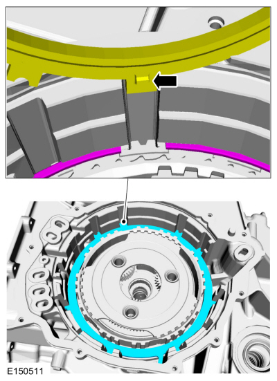
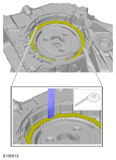
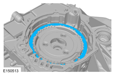
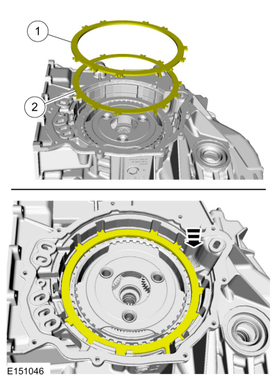
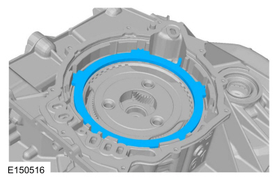
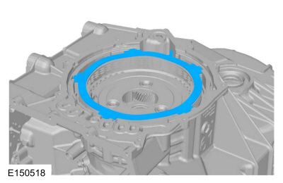
NOTE: The snap ring gap should be at the top of the transmission case.
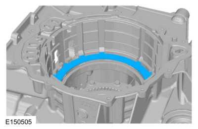
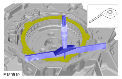
NOTE: The low One-Way Clutch (OWC) snap ring gap must be positioned as shown so that the low/reverse clutch pressure plate tab fits into the gap when it is installed later in this procedure.
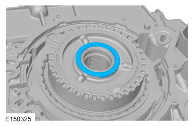
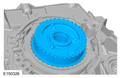
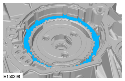
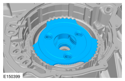
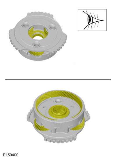
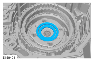
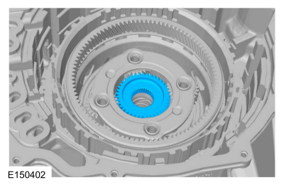
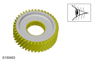
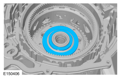
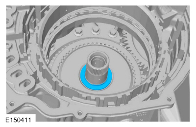
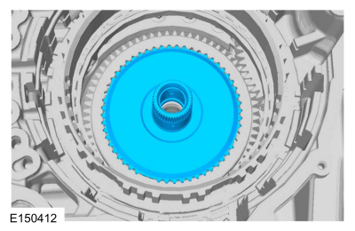
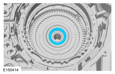
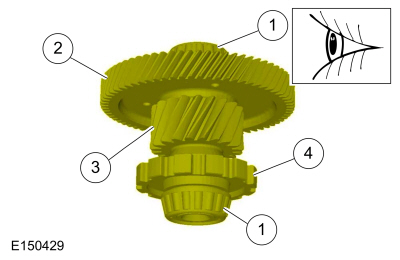
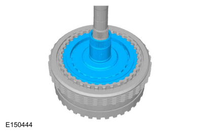
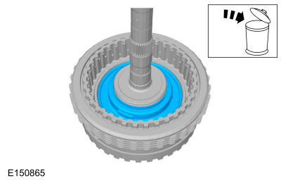
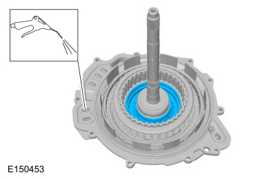
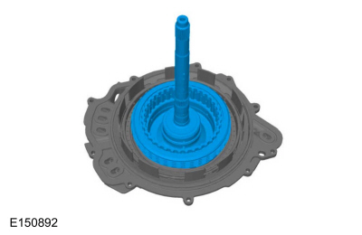
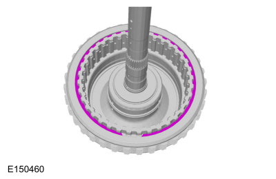
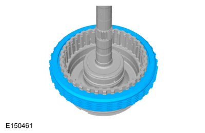
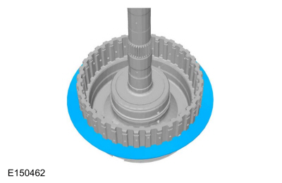
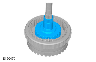
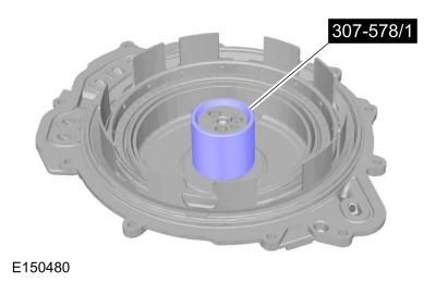
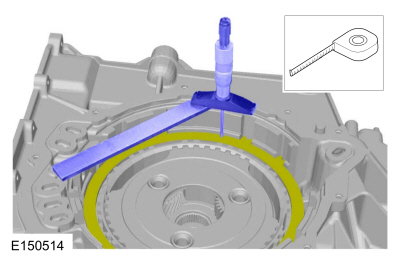
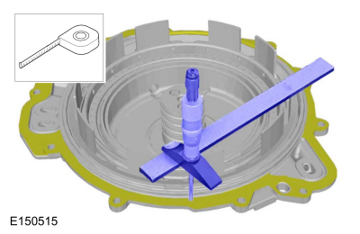
NOTE: The groove on the center sun gear is installed facing up.
NOTICE: Failure to align the tab on the bottom of the low/reverse pressure plate with the gap in the low One-Way Clutch (OWC) snap ring may result in damage to the transmission.
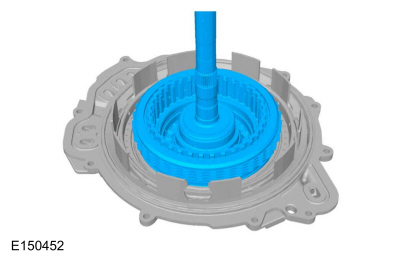
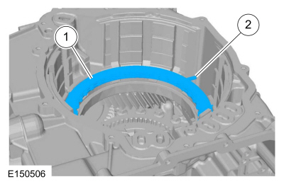
NOTE: The low/reverse clutch wave spring and pressure plate are temporarily reversely installed to measure the low/reverse clutch clearance.
NOTE: Temporarily install the low/reverse clutch wave spring and pressure plate with the pressure plate on top of the wave spring.
NOTE: When the low/reverse clutch is correctly installed, the wave spring is on top.
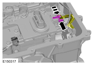
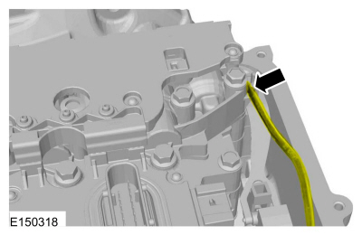
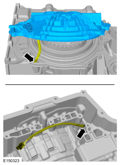
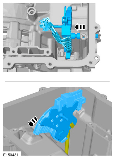
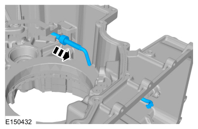
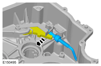
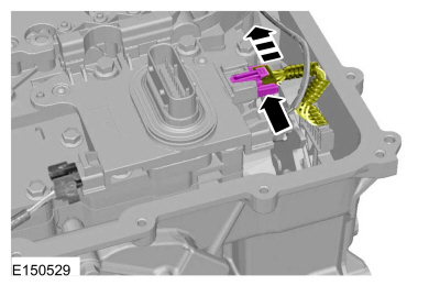
NOTICE: Be careful not to pinch the TSS , OSS or TR sensor wiring harnesses under the valve body, or damage to the wiring harness or connectors may occur.
NOTE: Make sure that the manual pin (part of the TR sensor) is correctly installed in the manual valve.
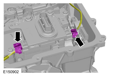
NOTICE: Make sure not to pinch the TSS , OSS or TR sensor wiring harnesses behind the solenoid body when positioning the solenoid body in place.
NOTE: Hand-tighten only.
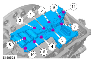
NOTE: Install the studbolts in the correct locations as noted during disassembly.
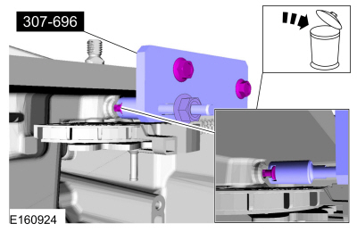
NOTICE: Only thread the bolts 6 to 8 turns or do not exceed 12 mm (0.472 in) in the torque converter. If the bolts are threaded too far, damage to the torque converter clutch surface can occur, causing torque converter failure.
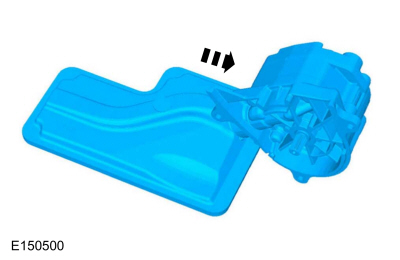
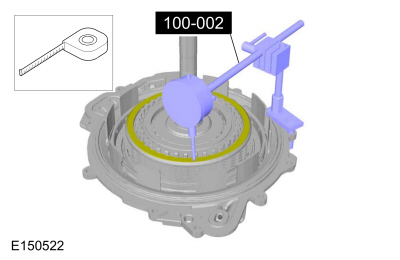
Install two 10 mm x 1.50 bolts into the torque converter 6 to 8 turns to assist in handling the torque converter and install the torque converter in the transmission.Copyright © Ford Motor Company