Diagnostics in this manual assume a certain skill level and knowledge of Ford-specific diagnostic practices.
REFER to:
Diagnostic Methods
(100-00 General Information, Description and Operation).
Diagnostics in this manual assume a certain skill level and knowledge of Ford-specific diagnostic practices.
REFER to:
Diagnostic Methods
(100-00 General Information, Description and Operation).
PINPOINT TEST A : THE HORN IS INOPERATIVE
| A1
CHECK THE BCM (BODY CONTROL MODULE)
OUTPUT
|
-
Using a diagnostic scan tool, view
Parameter Identifications (PIDs).
-
Select the active command
HORN Parameter Identification (PID) and command the horn ON and then OFF.
Does the horn sound when commanded on?
| No
|
VERIFY the
fuse 48 (20A) is OK. If OK, GO to
A8
If not OK, REFER to the Wiring Diagrams manual to identify the possible causes of the circuit short.
|
|
| A2
CHECK HORN OPERATION WITH HORN SWITCH CIRCUITS ISOLATED
|
|
NOTE:
Test is carried out with jumper at female (harness) side of connector.
-
 WARNING:
Turn the ignition OFF and wait one minute to deplete the backup power supply. Failure to follow this instruction may result
in serious personal injury or death in the event of an accidental deployment.
Ignition OFF and wait one minute. WARNING:
Turn the ignition OFF and wait one minute to deplete the backup power supply. Failure to follow this instruction may result
in serious personal injury or death in the event of an accidental deployment.
Ignition OFF and wait one minute.
-
Remove the driver airbag module.
REFER to:
Driver Airbag
(501-20B Supplemental Restraint System, Removal and Installation).
-
Connect a fused jumper wire:
|
Positive Lead
|
Measurement / Action
|
Negative Lead
|
|
C2414A-1
|

|
C2414D-4
|
Does the horn sound?
| Yes
|
REMOVE the fused jumper wire. GO to
A6
|
| No
|
REMOVE the fused jumper wire. GO to
A3
|
|
| A3
CHECK THE HORN CIRCUIT FOR A SHORT TO VOLTAGE
|
-
Measure:
|
Positive Lead
|
Measurement / Action
|
Negative Lead
|
|
C2414A-1
|

|
Ground
|
Is any voltage present?
|
| A4
CHECK THE HORN CIRCUIT FOR AN OPEN
|
-
Measure:
|
Positive Lead
|
Measurement / Action
|
Negative Lead
|
|
C2414A-1
|

|
C2280G-18
|
Is the resistance less than 3 ohms?
|
| A5
CHECK THE HORN SWITCH GROUND CIRCUIT FOR AN OPEN
|
-
Measure:
|
Positive Lead
|
Measurement / Action
|
Negative Lead
|
|
C2414A-1
|
|
Ground
|
Is the resistance less than 3 ohms?
|
| A6
CHECK HORN OPERATION WITH CLOCKSPRING ISOLATED
|
|
NOTE:
Test is carried out with jumper at male (clockspring) side of connector.
-
Disconnect Clockspring C218B
.
-
Connect a fused jumper wire:
|
Positive Lead
|
Measurement / Action
|
Negative Lead
|
|
C218B-4
|
|
C218B-11
|
Does the horn sound?
| Yes
|
REMOVE the fused jumper wire. GO to
A7
|
| No
|
INSTALL a new clockspring.
REFER to:
Clockspring
(501-20B Supplemental Restraint System, Removal and Installation).
|
|
| A7
CHECK HORN OPERATION WITH STEERING WHEEL HARNESS ISOLATED
|
|
NOTE:
Switch harness may be temporarily removed from airbag assembly for test purposes.
-
Connect Clockspring C218B
.
-
Disconnect Horn Switch C217A
.
-
Disconnect Horn Switch C217B
.
-
Connect a fused jumper wire:
|
Positive Lead
|
Measurement / Action
|
Negative Lead
|
|
C217A-1
|
|
C217B-1
|
Does the horn sound?
| Yes
|
INSTALL a new driver airbag module.
REFER to:
Driver Airbag
(501-20B Supplemental Restraint System, Removal and Installation).
|
| No
|
INSTALL a new steering wheel.
REFER to:
Steering Wheel
(211-04 Steering Column, Removal and Installation).
|
|
| A8
CHECK THE HORN RELAY
|
-
Carry out the relay component test.
Refer to Wiring Diagrams Cell 149 for schematic and connector information.
Did the relay pass the component test?
| No
|
INSTALL a new horn relay.
|
|
| A9
CHECK THE HORN OPERATION WITH RELAY CONTROL ISOLATED
|
-
Connect a fused jumper wire:
|
Positive Lead
|
Measurement / Action
|
Negative Lead
|
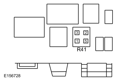 Pin socket 3
|
|
Pin socket 5
|
Does the horn sound?
| Yes
|
REMOVE the fused jumper wire. GO to
A10
|
| No
|
REMOVE the fused jumper wire. GO to
A12
|
|
| A10
CHECK THE HORN OPERATION WITH BCM (BODY CONTROL MODULE)
ISOLATED
|
-
Connect a fused jumper wire:
|
Positive Lead
|
Measurement / Action
|
Negative Lead
|
|
C2280C-20
|
|
Ground
|
Does the horn sound?
| Yes
|
REMOVE the fused jumper wire. GO to
A15
|
| No
|
REMOVE the fused jumper wire. GO to
A11
|
|
| A11
CHECK THE HORN RELAY VOLTAGE SUPPLY CIRCUIT FOR VOLTAGE
|
-
Measure:
|
Positive Lead
|
Measurement / Action
|
Negative Lead
|
|
Pin socket 2
|
|
Ground
|
Is the voltage greater than 11 volts?
| Yes
|
REPAIR circuit CRH02 (BU/WH).
|
| No
|
REPAIR the horn relay voltage supply circuit.
|
|
| A12
CHECK THE HORN RELAY LOAD CIRCUIT FOR VOLTAGE
|
-
Measure:
|
Positive Lead
|
Measurement / Action
|
Negative Lead
|
|
Pin socket 3
|
|
Ground
|
Is the voltage greater than 11 volts?
|
| A13
CHECK FOR VOLTAGE AT THE HORN
|
-
Press and hold the horn switch.
-
Measure:
|
Positive Lead
|
Measurement / Action
|
Negative Lead
|
|
C131-2
|
|
Ground
|
Is the voltage greater than 11 volts?
|
| A14
CHECK THE HORN GROUND CIRCUIT FOR AN OPEN
|
-
Press and hold the horn switch.
-
Measure:
|
Positive Lead
|
Measurement / Action
|
Negative Lead
|
|
C131-2
|
|
C131-1
|
Is the voltage greater than 11 volts?
| Yes
|
INSTALL a new horn.
REFER to:
Horn
(413-06 Horn, Removal and Installation).
|
|
| A15
CHECK FOR CORRECT BCM (BODY CONTROL MODULE)
OPERATION
|
-
Disconnect and inspect the
connectors.
-
Repair:
-
corrosion (install new connector or terminals – clean module pins)
-
damaged or bent pins – install new terminals/pins
-
pushed-out pins – install new pins as necessary
-
Reconnect the
connectors. Make sure they seat and latch correctly.
-
Operate the system and determine if the concern is still present.
Is the concern still present?
| Yes
|
CHECK
for any applicable Technical Service Bulletins (TSBs). If a
exists for this concern, DISCONTINUE this test and FOLLOW
instructions. If no Technical Service Bulletins (TSBs) address this concern, INSTALL a new
.
REFER to:
Body Control Module (BCM)
(419-10 Multifunction Electronic Modules, Removal and Installation).
|
| No
|
The system is operating correctly at this time. The concern may have been caused by module connections. ADDRESS the root cause
of any connector or pin issues.
|
|
PINPOINT TEST B : THE HORN IS ALWAYS ON
| B1
ISOLATE THE HORN RELAY
|
Does the horn continue to sound?
| Yes
|
DISCONNECT the horn to prevent damage from continuous operation. REPAIR the short in circuit CRH04 (VT/GN).
|
|
| B2
CHECK THE HORN RELAY
|
-
Carry out the relay component test.
Refer to Wiring Diagrams Cell 149 for schematic and connector information.
Did the relay pass the component test?
| No
|
INSTALL a new horn relay.
|
|
| B3
ISOLATE THE BCM (BODY CONTROL MODULE)
HORN OUTPUT CIRCUIT
|
Does the horn continue to sound?
| Yes
|
REPAIR the short in circuit CRH02 (BU/WH).
|
|
| B4
ISOLATE THE BCM (BODY CONTROL MODULE)
HORN INPUT CIRCUIT
|
Does the horn continue to sound?
|
| B5
CHECK THE HORN SWITCH INPUT FOR A SHORT TO GROUND
|
Does the horn continue to sound?
| Yes
|
REPAIR the short in circuit RRH02 (GN/WH).
|
|
| B6
CHECK THE CLOCKSPRING FOR A SHORT TO GROUND
|
-
WARNING:
Turn the ignition OFF and wait one minute to deplete the backup power supply. Failure to follow this instruction may result
in serious personal injury or death in the event of an accidental deployment.
Ignition OFF and wait one minute.
-
Remove the driver airbag.
REFER to:
Driver Airbag
(501-20B Supplemental Restraint System, Removal and Installation).
-
Disconnect Clockspring C218B
.
Does the horn continue to sound?
| Yes
|
INSTALL a new clockspring.
REFER to:
Clockspring
(501-20B Supplemental Restraint System, Removal and Installation).
|
|
| B7
CHECK THE HORN SWITCH
|
-
Connect Clockspring C218B
.
-
Disconnect Horn Switch C217A
.
Does the horn continue to sound?
| Yes
|
INSTALL a new steering wheel.
REFER to:
Steering Wheel
(211-04 Steering Column, Removal and Installation).
|
| No
|
INSTALL a new driver airbag module.
REFER to:
Driver Airbag
(501-20B Supplemental Restraint System, Removal and Installation).
|
|
| B8
CHECK FOR CORRECT BCM (BODY CONTROL MODULE)
OPERATION
|
-
Disconnect and inspect the
connectors.
-
Repair:
-
corrosion (install new connector or terminals – clean module pins)
-
damaged or bent pins – install new terminals/pins
-
pushed-out pins – install new pins as necessary
-
Reconnect the
connectors. Make sure they seat and latch correctly.
-
Operate the system and determine if the concern is still present.
Is the concern still present?
| Yes
|
CHECK
for any applicable Technical Service Bulletins (TSBs). If a
exists for this concern, DISCONTINUE this test and FOLLOW
instructions. If no Technical Service Bulletins (TSBs) address this concern, INSTALL a new
.
REFER to:
Body Control Module (BCM)
(419-10 Multifunction Electronic Modules, Removal and Installation).
|
| No
|
The system is operating correctly at this time. The concern may have been caused by module connections. ADDRESS the root cause
of any connector or pin issues.
|
|