| 211-05 Steering Wheel and Column Electrical Components | 2013 - 2014 MKZ |
| Description and Operation | Procedure revision date: 11/7/2012 |
System Operation
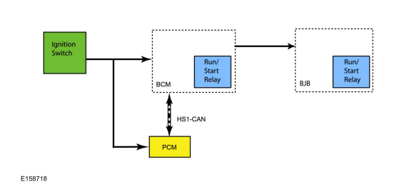
System Diagram - Push Button Start
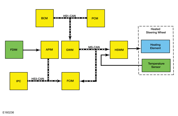
System Diagram - Heated Steering Wheel
Network Message Chart - Push Button Start
Module Network Input Messages - SCCM
| Broadcast Message | Originating Module | Message Purpose |
|---|---|---|
| Ignition status | GWM | This message informs the BCM of the current ignition status; off, accessory, run, start, unknown or invalid. |
Module Network Input Messages - BCM
| Broadcast Message | Originating Module | Message Purpose |
|---|---|---|
| RKE data | RTM | Provides the BCM with the RKE commands and passive key information. |
Network Message Chart - Heated Steering Wheel
Module Network Input Messages - HSWM
| Broadcast Message | Originating Module | Message Purpose |
|---|---|---|
| Engine power status | PCM | This message indicates to the HSWM whether the engine is running. |
| Ignition status | BCM | Indicates which ignition state is active. |
| Transport mode | BCM | Message is used to reduce the drain on the battery during long periods when the vehicle is not used, such as shipping from the factory to the dealership. |
| Steering wheel heat request | FCIM | Message is used to activate the heated steering wheel when the soft button is pressed on the FDIM , or when the conditions are met to activate the heated steering wheel (and heated seats) during a remote start. |
Module Network Input Messages - FCIM
| Broadcast Message | Originating Module | Message Purpose |
|---|---|---|
| Heated steering wheel button status | APIM | This message informs the FCIM that the heated steering wheel soft button was pressed on the FDIM . |
| Ambient exterior temperature data | IPC | This message is used by the FCIM when determining if outside conditions are cold enough to request the heated steering wheel be activated during remote start operation. |
OFF
To enter OFF mode, press the ignition switch without pressing the brake pedal while the vehicle is in ON mode or the engine is running. The passive key does not have to be in the vehicle to achieve OFF mode. However, the passive key must be present to achieve any other ignition mode.
When the engine is running and any one of the vehicle doors is opened and then closed, the presence of a passive key is determined. If the passive key is not present, the message center displays NO KEY DETECTED to alert the driver the passive key is not present.
When the ignition switch is turned to the OFF position, the BCM communicates the ignition mode to the other modules by sending an ignition status message over the CAN .
ON
To enter ON mode, with a valid passive key inside the vehicle, press the ignition switch for a minimum of one second without pressing the brake pedal. Once the BCM and RTM indicate a valid passive key is present inside the vehicle and the BCM has detected the ignition switch input without the stoplamp switch input, the BCM activates the internal run/start relay and the BJB run/start relay, providing ignition voltage to the various vehicle systems and modules. The BCM communicates the ignition mode to the other modules by sending an ignition status message over the CAN .
START
To enter START mode, with a valid passive key inside the vehicle, press and hold the brake pedal. Then press and release the ignition switch. Once the BCM and RTM indicate a valid passive key is present inside the vehicle and the BCM has detected the ignition switch input with the stoplamp switch input, the BCM activates the internal run/start relay and the BJB run/start relay, providing ignition voltage to the various vehicle systems and modules. At this time, the PCM also receives an input from the ignition switch, initiating a sequence that ends with the starter motor activating. The BCM communicates the ignition mode to the other modules by sending an ignition status message over the CAN .
The engine can be started from any ignition mode. Once the ignition has entered START mode, the indicator in the ignition switch illuminates.
Heated Steering Wheel
When the HSWM receives a request to heat the steering wheel, the HSWM applies voltage and ground to the steering wheel heating elements (integral to the steering wheel) to heat the steering wheel to a temperature of approximately 28-34°C (82-94°F). The heated steering wheel temperature is maintained by the HSWM using a temperature sensor in the steering wheel.
The HSWM is designed to remain on, heating the steering wheel and maintaining the temperature until switched off on the FDIM or the ignition is turned off.
The controls and indicators for the heated steering wheel system are located on the FDIM (touchscreen) only. The FDIM does not communicate on any network and is connected directly to the APIM .
Remote Start System
The heated steering wheel system (along with the heated front seats) may be configured through the message center to activate when the remote start feature is used, based on outside air temperature. During remote start, the outside air temperature is continually evaluated by the HVAC system. The heated steering wheel system activation changes if the outside air changes from cold to moderate or warm temperatures or back from moderate or warm to cold temperatures.
Field Effect Transistor (FET) Protection
A Field Effect Transistor (FET) is a type of transistor that, when used with module software, monitors and controls current
flow on module outputs. The Field Effect Transistor (FET) protection strategy prevents module damage in the event of excessive
current flow. For additional information about Field Effect Transistor (FET) protection,
Refer to:
Module Controlled Functions - System Operation and Component Description
(419-10 Multifunction Electronic Modules, Description and Operation).
Component Description
Multifunction Switch
The multifunction switch is a multiple position switch controlled by a lever. The multifunction switch controls the turn signal,
headlamp low/high beam and headlamp dimmer/flash-to-pass functions.
Refer to:
Exterior Lighting - System Operation and Component Description
(417-01 Exterior Lighting, Description and Operation).
Wiper and Washer Switch
The wiper and washer switch is a multiple position switch controlled by a lever. The wiper and washer switch controls the
front windshield wipers and washers.
Refer to:
Wipers and Washers - Overview
(501-16 Wipers and Washers, Description and Operation).
Steering Wheel Switches
The steering wheel switches are comprised of an upper and lower switch cluster mounted on each side of the steering wheel, facing the driver. The upper and lower switch clusters can be serviced separately on each side.
The
LH
upper switch cluster controls the message center display.
Refer to:
Message Center - Overview
(413-01 Instrumentation, Message Center and Warning Chimes, Description and Operation).
The
LH
lower switch cluster controls the cruise control system.
Refer to:
Cruise Control - System Operation and Component Description
(419-03A Cruise Control, Description and Operation).
The RH upper and lower switch clusters control the audio and SYNC® systems.
Front PATS Antenna
If the battery inside the passive key is weak, damaged or if excessive ambient Radio Frequency Interference (RFI) prevents
communication between the
RTM
and the passive key, the backup slot located in the center console storage compartment provides a secondary means for the
BCM
to validate the passive key and authorize the use of the vehicle. The front
PATS
antenna uses passive Radio Frequency (RF) identification to exchange signals with the passive key.
Refer to:
Passive Anti-Theft System (PATS) - System Operation and Component Description
(419-01B Passive Anti-Theft System (PATS) - Vehicles With: Push Button Start, Description and Operation).
Stoplamp Switch
The stoplamp switch is a dual contact switch. One set of contacts is normally open and receives voltage at all times. The other set of contacts is normally closed and is connected to ground.
When the normally open contacts close, the voltage is sent to the BCM and PCM .
When the normally closed contacts open, the ground circuit to the PCM is momentarily interrupted.
Ignition Switch
The ignition switch is a momentary dual contact switch that is hard-wired to the BCM and PCM . Both sets of contacts are normally open and receive voltage at all times. When the ignition switch is pressed, one set of contacts supplies ground to the BCM and the other set of contacts supplies voltage to the PCM . The ignition switch also uses a LED to illuminate the switch.
The ignition switch is part of the GSM and cannot be serviced separately.
BCM
The
BCM
determines the vehicle ignition mode based on the ignition switch input, the stoplamp switch input and
RTM
messages. The
BCM
communicates the ignition mode to the other modules over the
CAN
. The
BCM
monitors the ignition switch input and the ignition mode outputs. If a fault is detected in the ignition system, Diagnostic
Trouble Codes (DTCs) are set in the
BCM
.
Refer to:
Module Controlled Functions - System Operation and Component Description
(419-10 Multifunction Electronic Modules, Description and Operation).
RTM
Refer to:
Module Controlled Functions - System Operation and Component Description
(419-10 Multifunction Electronic Modules, Description and Operation).
HSWM
The HSWM controls the steering wheel heating elements. The HSWM uses the steering wheel temperature sensor to maintain the steering wheel temperature. The HSWM is designed to remain on, heating the steering wheel and maintaining temperature until switched off on the FDIM or the ignition is turned off.
The HSWM requires PMI when replaced.
FDIM
The controls and indicators for the heated steering wheel system are located in the
FDIM
(touchscreen) only. For additional information about the
FDIM
,
Refer to:
Information and Entertainment System - System Operation and Component Description
(415-00A Information and Entertainment System - General Information - Vehicles With: Touchscreen Display, Description and Operation).
Refer to:
Information and Entertainment System - System Operation and Component Description
(415-00B Information and Entertainment System - General Information - Vehicles With: THX Audio System, Description and Operation).
Steering Wheel
The steering wheel heater elements are integral to the steering wheel and cannot be serviced separately. The HSWM uses the steering wheel heater elements to heat the steering wheel.
The steering wheel temperature sensor is part of the steering wheel and cannot be serviced separately. The HSWM uses the steering wheel temperature sensor to monitor the steering wheel temperature.
Copyright © Ford Motor Company