| 415-00A Information and Entertainment System - General Information - Vehicles With: Touchscreen Display | 2013 - 2014 MKZ |
| Description and Operation | Procedure revision date: 11/21/2012 |
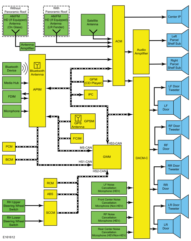
System Operation
System Diagram
Network Message Chart
A missing network message is indicated by a U-code
DTC
and can be the result of intermittent concerns such as damaged wiring or low battery voltage occurrences. Additionally, vehicle
repair procedures such as module reprogramming can set these Diagnostic Trouble Codes (DTCs). When a missing message
DTC
(U-code) sets, it is important to look for symptoms present in the audio system and throughout the vehicle, and to review
the complete message list to determine which other modules rely on the same message.
Refer to:
Communications Network
(418-00 Module Communications Network, Diagnosis and Testing).
See
CAN
Multiplex Messages.
When the other modules have been identified, run the self-test for those modules. If the same message is missing from those modules, the identical, or similar lost communication Diagnostic Trouble Codes (DTCs) may be set in those modules. Confirmation of missing messages common to multiple modules can indicate that the originating module is the source of the concern, or that the communication network may be at fault.
It is very important to understand the following:
Module Network Input Messages - ACM
| Broadcast Message | Originating Module | Message Purpose |
|---|---|---|
| Audio settings | IPC | Used to set the radio listening source ( AM / FM , Satellite, HD Radio® – if equipped) from the steering wheel switch. |
| Audio source select | IPC | Used to set the audio system listening source ( AM / FM , CD , etc.) from the steering wheel switch through the IPC RH infotainment display. |
| Belt-Minder® audio mute | IPC | Used to mute speaker output so the Belt-Minder® tone can be more easily heard. This message only applies to vehicles with a MyKey® enabled and in use. The audio system is muted until the safety belt(s) are buckled. |
| CD request signals | GFM ( CD player) | Used to request audio source priority when the CD listening source is selected. |
| Day/night status | BCM | Used for day/night illumination status for the audio system. |
| Ignition status | BCM | Used to indicate the ignition state (OFF, ACCESSORY, RUN, and START) required for ACM operating modes and fault reporting. |
| Instrument panel cluster chime | IPC | Used to request a warning chime to be played through the audio system. |
| MyKey® volume limit status | IPC | Used to limit the maximum audio system volume when a MyKey® restricted key is in use. |
| Power mode | IPC | Used to disable the functionality of the ACM due to the load shedding feature. |
| Power up chime modules | IPC | Used to initiate the audio system as the chime source. |
| Vehicle configuration data | BCM | Used to verify vehicle configuration data such as the VIN and system module configuration. |
Module Network Input Messages - APIM
| Broadcast Message | Originating Module | Message Purpose |
|---|---|---|
| Airbag deployment status | RCM | Used to monitor airbag deployment status for 911 Assist™. |
| Audio settings | IPC | Used to set the radio listening source ( AM / FM , Satellite, HD Radio® – if equipped) from the steering wheel switch through the IPC RH infotainment display. |
| Day/night status | BCM | Used for day/night illumination status for the FDIM . |
| Display language selection | IPC | Used to display information on the FDIM in the selected language. |
| eCall notification | RCM | Used to notify of a 911 Assist™ call being initiated due to airbag deployment. |
| FCIM bezel diagnostic status | GWM | Used to display the requested bezel diagnostics operations in the centerstack infotainment display. |
| FCIM button state | FCIM | Used to indicate when a button is pressed on the FCIM so the audio system can make the desired setting change. |
| Gear lever position | IPC | Used to verify the gear selector position for bezel diagnostics. |
| GPS compass direction | GPSM | Used to display the compass direction on the FDIM . |
| GPS data | GPSM | Used for vehicle positioning, heading, and direction for navigation and 911 Assist™. |
| Ignition key type | BCM | Used to determine if a MyKey® is enabled and in use. |
| Ignition status | BCM | Used to indicate the ignition state (OFF, ACCESSORY, RUN, and START) required for APIM operating modes and fault reporting. |
| MyKey® volume limit status | IPC | Used to limit the maximum audio system volume when a MyKey® restricted key is in use. |
| Navigation rolling wheel count and direction | ABS module | Used to provide more accurate vehicle position tracking when the GPS signal is temporarily unavailable. |
| Steering wheel switch status | SCCM | Used to indicate the button press status of the steering wheel switches. |
| Vehicle configuration data | BCM | Used to verify vehicle configuration data such as the VIN and system module configuration. |
| Vehicle speed | PCM | Used for navigation functionality. |
Module Network Input Messages - DACMC
| Broadcast Message | Originating Module | Message Purpose |
|---|---|---|
| Accelerator pedal position | PCM | Used to determine the throttle position status for the active noise control system. |
| Luggage compartment lid ajar status | BCM | Used to determine the luggage compartment lid ajar status for the active noise control system. |
| Driver's door ajar status | BCM | Used to determine the driver's door ajar status for the active noise control system. |
| Engine status | GWM | Used to determine if the engine is on, off, or auto-stopped for active noise control functions. |
| Ignition status | GWM | Used to indicate the ignition state (OFF, ACCESSORY, RUN, and START) required for DACMC operating modes and fault reporting. |
| Passenger door ajar status | BCM | Used to determine the RH front door ajar status for the active noise control system. |
| Power up chime modules | IPC | Used to initiate the audio system as the chime source. |
Module Network Input Messages - FCIM
| Broadcast Message | Originating Module | Message Purpose |
|---|---|---|
| Audio source selection | ACM | Used to indicate the selected audio system source. |
| Day/night status | BCM | Used for day/night illumination status for the FCIM . |
| Ignition status | BCM | Used to indicate the ignition state (OFF, ACCESSORY, RUN, and START) required for FCIM operating modes and fault reporting. |
| Power mode | IPC | Used to disable the functionality of the FCIM due to the load shedding feature. |
| Vehicle configuration data | BCM | Used to verify vehicle configuration data such as the VIN and system module configuration. |
Module Network Input Messages - GFM ( CD Player)
| Broadcast Message | Originating Module | Message Purpose |
|---|---|---|
| CD display | APIM | Used to control the CD functions from the FDIM touchscreen. |
| CD multifunction control | IPC | Used to control the CD functions from the steering wheel switches through the IPC RH infotainment display. |
Module Network Input Messages - GPSM
| Broadcast Message | Originating Module | Message Purpose |
|---|---|---|
| Ignition status | BCM | Used to indicate the ignition state (OFF, ACCESSORY, RUN, and START) required for GPSM operating modes and fault reporting. |
| Vehicle configuration data | BCM | Used to verify vehicle configuration data such as the VIN and system module configuration. |
| Vehicle yaw rate | RCM | Used to verify the vehicle acceleration data for navigation. |
| Wheel rotation count | BCM | Used to provide more accurate vehicle position tracking when the GPS signal is temporarily unavailable. |
| Wheel rotation direction | BCM | Used to determine wheel rotation direction for navigation. |
Module Network Input Messages - IPC
| Broadcast Message | Originating Module | Message Purpose |
|---|---|---|
| Audio source selection | ACM | Used to display the selected audio source on the IPC . |
| CD function status | GFM ( CD player) | Used to indicate the loading status of a CD . |
| Display language request | APIM | Used to display information on the IPC in the selected language. |
| Multimedia player total play time status | APIM | Used to indicate the total play time of the audio track being played. |
Accessory Delay Feature
The accessory delay feature allows the audio system to be operated for a preset period of time after the ignition is turned off and a front door has not been opened.
Active Noise Control
Active noise control is an audio system feature that eliminates some of the low frequency engine noise within the passenger compartment typically induced under wide open throttle or heavy part-throttle conditions. The system uses 2 (non- HEV ) or 3 ( HEV ) microphones, a DACMC , and the audio system speakers. The DACMC determines the noise frequency to be canceled based upon engine rotation speed data from the PCM and the microphone input signals.
While the engine is running, the noise cancellation microphones located in the front and rear of the headliner monitor the engine noise resonating in the passenger compartment. The microphones transmit this noise as analog signals to the DACMC , where they are converted into digital signals by the integrated analog/digital converter. The digital signals are processed and an inverted phase sound wave with the same amplitude as the original sound is created. This new sound is converted into an analog audio signal and output by the DACMC internal tone generator to all of the speakers except the instrument panel center speaker and the left and right parcel shelf subwoofer speakers.
AM / FM Radio
The AM / FM antenna receives analog radio waves and sends them through the audio unit antenna amplifier (without panoramic roof) and AM / FM antenna coaxial cable to the ACM . The radio waves are converted into fluctuating AC voltage and sent as left and right analog audio signals to the audio amplifier, DACMC , and instrument panel center speaker. The audio amplifier processes the audio signals and sends them to the left and right parcel shelf subwoofer speakers as fluctuating AC voltage. The DACMC processes the audio signals and sends them to all of the speakers except the instrument panel center speaker and the left and right parcel shelf subwoofer speakers as fluctuating AC voltage.
APIM Programming
The APIM requires specific programming procedures for correct operation. APIM programming is required when:
There are 3 types of APIM programming available:
There are 3 types of software installation methods:
NOTE: Vehicle Interface Processor (VIP) programming is not selectable because the Vehicle Interface Processor (VIP) is configured automatically during programming.
There are some general programming guidelines that are applicable to multiple types of programming:
To perform module replacement programming,
Refer to:
SYNC Module [APIM] Replacement Programming
(415-00A Information and Entertainment System - General Information - Vehicles With: Touchscreen Display, General Procedures).
To perform standard programming,
Refer to:
SYNC Module [APIM] Standard Programming
(415-00A Information and Entertainment System - General Information - Vehicles With: Touchscreen Display, General Procedures).
To perform custom programming,
Refer to:
SYNC Module [APIM] Custom Programming
(415-00A Information and Entertainment System - General Information - Vehicles With: Touchscreen Display, General Procedures).
Audio Extended Play
This feature allows the audio system to operate with the ignition OFF, regardless of door latch position. When the power button on the FCIM is pressed, audio system functionality is enabled and remains active for a period of 20-60 minutes, depending on configuration settings. To turn the audio system off, the power button on the FCIM is pressed. Audio extended play will not function if the battery load shed is active.
Battery Load Shed
The BCM uses the battery current sensor to monitor the battery state of charge. The battery current sensor is attached to the battery ground cable. With the ignition in RUN, ACC, or OFF, a load shed message is sent over the CAN when the BCM determines that the battery state of charge is below 40%, 45 minutes have elapsed, or 10% of the charge has been drained. This message turns off the audio system to save the remaining battery charge. Under this condition, SYS OFF TO SAVE BATT is displayed on the centerstack infotainment display to notify the driver that battery protection actions are active. To clear the load shed state, start the vehicle.
Bluetooth Mode
Bluetooth is a secure, short-range radio frequency that allows devices to communicate wirelessly through radio waves. The operating range of a Bluetooth signal is application specific, but will have a minimum range of 10 meters (33 feet).
The Bluetooth interface can accommodate both Bluetooth-enabled mobile phones and Bluetooth-enabled media devices. The SYNC® system allows interaction with several types of customer Bluetooth devices, including mobile phones and media devices. The APIM contains an on-board Bluetooth chipset, which enables certain wireless devices to interact with the system.
Any Bluetooth device used with the SYNC® system must first be paired with the APIM on-board Bluetooth chipset before it can become operational. Pairing a Bluetooth device is accomplished through the "Add Device" selection of the phone menu. When pairing a device, the SYNC® system generates a unique PIN that must be entered on the Bluetooth device in order for the pairing process to be successful. There are also some device-specific actions that must take place. For information on the pairing process, refer to the Owner's Literature.
Only one Bluetooth phone and one Bluetooth media device can be connected to the system at any one time. If an additional device of either type is paired and made active, the APIM disconnects any active connection and establishes a connection with the new device.
It is important to understand that while most Bluetooth devices can pair with the SYNC® system, not all Bluetooth devices have the same level of features available when interacting with the SYNC® system. To determine if a Bluetooth device or feature is supported, review the device compatibility list. Refer to www.syncmyride.com.
Compass
The GPS antenna integral to the GPSM is used to acquire the compass heading. The compass heading is sent over the CAN to be displayed on the centerstack infotainment display.
Composite Audio-Video Input Mode
The composite audio and video inputs consist of the RCA jack connections that are used for playing video or audio content from an external device such as a gaming system.
HD Radio® - If Equipped
HD Radio® is a subscription-free service.
HD Radio® technology allows an AM or FM radio station to duplicate their traditional analog channel with a matching digital channel. Some FM radio stations subdivide the digital output signal into multiple channels that are not duplicates of the analog channel. These extra multicast channels vary in availability and are called HD2, HD3 and HD4 channels.
The AM / FM antenna receives radio waves containing metadata (information such as station call letters, artist, album title, song title, and genre) and digital HD Radio® audio. The radio waves are sent through the audio unit antenna amplifier (without panoramic roof) and AM / FM antenna coaxial cable to the HD Radio® receiver built into the ACM . The metadata is separated from the audio. The metadata is sent to be displayed on the centerstack infotainment display, and the audio is converted into fluctuating AC voltage and sent as left and right analog audio signals to the audio amplifier, DACMC , and instrument panel center speaker. The audio amplifier processes the audio signals and sends them to the left and right parcel shelf subwoofer speakers as fluctuating AC voltage. The DACMC processes the audio signals and sends them to all of the speakers except the instrument panel center speaker and the left and right parcel shelf subwoofer speakers as fluctuating AC voltage.
MyKey® Audio Operation
When a MyKey® is in use, the following restrictions are activated:
Refer to the Owner's Literature for more information on MyKey®.
Navigation
The navigation system guides the user to a pre-entered destination. Map data is transmitted from the map data Secure Digital (SD) card inserted into the media hub to the APIM through the USB cable. The APIM calculates route information based on GPS data received by the GPSM . The APIM also uses vehicle speed and transmission gear selected signals received through the network to detect vehicle speed and direction, resulting in more accurate navigation tracking. The navigation display is shown on the FDIM .
The voice recognition system allows the user to interface with the system without using the FDIM . A microphone located in the headliner provides a direct input to the APIM .
Satellite Radio
Satellite radio is a subscription-based service.
The satellite radio antenna receives signals containing metadata (information such as station call letters, artist, album title, song title, and genre) and digital satellite radio audio. These signals are sent through the satellite radio antenna coaxial cable to the satellite radio receiver built into the ACM . The metadata is separated from the audio. The metadata is sent to be displayed on the centerstack infotainment display, and the audio is converted into fluctuating AC voltage and sent as left and right analog audio signals to the audio amplifier, DACMC , and instrument panel center speaker. The audio amplifier processes the audio signals and sends them to the left and right parcel shelf subwoofer speakers as fluctuating AC voltage. The DACMC processes the audio signals and sends them to all of the speakers except the instrument panel center speaker and the left and right parcel shelf subwoofer speakers as fluctuating AC voltage.
Secure Digital (SD) Card Mode
When a Secure Digital (SD) card not containing map data is connected to the vehicle audio system through the Secure Digital (SD) card slot, audio from the card can be played through the vehicle speakers. Functions such as volume, seek, fast forward, pause, etc. can be controlled by the vehicle audio controls.
Image files can be saved to the APIM from a Secure Digital (SD) card in order to be used as wallpaper backgrounds displayed on the FDIM .
SIRIUS Data Services - If Equipped
SIRIUS Data Services is a subscription-based service and requires a separate subscription from the satellite radio. A map data Secure Digital (SD) card is also required.
The satellite radio antenna receives digital signals containing data. These signals are sent through the satellite radio antenna coaxial cable to the satellite radio receiver built into the ACM . The ACM sends the data signals to the APIM . The APIM sends them to the FDIM touchscreen to be displayed.
SIRIUS Data Services allows the customer to receive updates for:
Some services may be available separately while others are only available as packages.
Speed Compensated Volume
The ACM adjusts the audio system volume based on the VSS signal to compensate for speed and wind noise.
When a MyKey® is in use and the MyKey® radio volume limiter is enabled, the speed compensated volume is disabled.
Steering Wheel Switch Function
The RH steering wheel switches consist of an upper and a lower 5-way switch. The upper 5-way steering wheel switch operates the IPC infotainment display. The lower 5-way steering wheel switch operates the volume +/-, seek +/-, voice, and mute buttons functions.
SYNC® Services - If Equipped
SYNC® Services is a subscription-based service. For SYNC® Services subscription information, refer to www.syncmyride.com.
The customer's mobile phone is used to access and download the SYNC® Services. SYNC® Services information received by the customer's mobile device is sent to the APIM .
The GPS antenna, integral to the GPSM , is used to detect the location and direction of the vehicle.
SYNC® Services includes the following features:
SYNC® Services allows the customer to receive updates for:
SYNC® System
The SYNC® system is a hands-free communication and entertainment system that supports many features. All features are not available with every phone.
The SYNC® system provides the following abilities:
USB Mode
The USB port can be used for connecting a media device (such as an iPod®) with the device's available cable, or for directly plugging in a portable mass storage device, such as a thumb drive. When playing media files stored on a mass storage device, the SYNC® system only plays files that do not have Digital Rights Management (DRM) protection. The USB port can also be used for uploading vehicle Application upgrades. The USB port is powered by the APIM , so no external power source is needed to power a device plugged into the USB port if the device supports this feature.
In addition to audio information, metadata (information such as artist, album title, song title, and genre) may also be sent to the APIM from a device plugged into the USB port. The APIM uses the metadata to create indexes that can be used to sort for particular music based on customer preference. Not all USB devices can send metadata to the APIM . When a new media device is connected to the SYNC® system, the APIM automatically indexes the information. This may take several minutes (depending on the amount of data on the device), and is considered normal operation. When a device that was previously connected to the SYNC® system is reconnected, the APIM updates the index (rather than creating a new one), which reduces the amount of time needed to index the device.
Image files can be saved to the APIM from a USB device. These images can be displayed on the FDIM as wallpaper backgrounds.
Voice Recognition
Voice recognition minimizes driver distraction by allowing control of audio system and climate control system functions while driving so they do not need to be carried out by interaction with the centerstack infotainment display and/or device.
When the voice steering wheel switch is pressed, an audible prompt originating at the APIM is heard from the speakers. Based on the customer’s setting, audible prompts will either be a voice or a simple tone. When interaction mode is set to standard, detailed voice guidance is provided. When interaction mode is set to advanced, most prompts are tones only, and minimal voice guidance is provided. The microphone receives the voice commands and sends them to the APIM . Refer to the Owner's Literature for more information on voice recognition.
Component Description
ACM
The ACM can be operated with the ignition in RUN, ACC, or OFF.
The ACM receives radio waves containing audio from the antenna coaxial cables and converts them into fluctuating AC voltage. The ACM receives stereo and mono audio signals from the APIM , and stereo audio signals from the GFM ( CD player) in the form of fluctuating AC voltage. The ACM processes all inputs, and depending on the input received, sends stereo or mono analog audio signals to the audio amplifier, DACMC , and instrument panel center speaker. The audio amplifier processes the audio signals and sends them to the left and right parcel shelf subwoofer speakers as fluctuating AC voltage. The DACMC processes the audio signals and sends them to all of the speakers except the instrument panel center speaker and the left and right parcel shelf subwoofer speakers as fluctuating AC voltage.
The ACM receives radio waves containing satellite radio and HD Radio® (if equipped) data through the antenna coaxial cables. The data is sent to be displayed on the centerstack infotainment display.
The ACM requires PMI when it is replaced.
Antenna
If not equipped with a panoramic roof, an AM / FM on-glass antenna grid is used. It receives radio waves containing audio and sends them through the audio unit antenna amplifier and AM / FM antenna coaxial cable to the ACM .
If equipped with a panoramic roof, an AM / FM antenna mounted to the Left Rear (LR) fender is used. It receives radio waves containing audio and sends them through the AM / FM antenna coaxial cable to the ACM . The Left Rear (LR) fender-mounted antenna base has an integrated amplifier that is powered by the ACM . The integrated amplifier is used to amplify the AM / FM radio waves to improve reception.
If equipped with HD Radio® and not equipped with a panoramic roof, the AM / FM on-glass antenna grid receives radio waves containing digital audio and data. The radio waves are sent to the audio unit antenna amplifier and the radio waves containing digital audio are amplified to improve reception. The amplified radio waves containing audio and the radio waves containing data are sent through the AM / FM antenna coaxial cable to the ACM .
If equipped with HD Radio® and a panoramic roof, the AM / FM antenna mounted to the Left Rear (LR) fender receives radio waves containing digital audio and data. The radio waves are sent to the antenna base where the radio waves containing digital audio are amplified by the integrated amplifier to improve reception. The amplified radio waves containing audio and the radio waves containing data are sent through the AM / FM antenna coaxial cable to the ACM .
Satellite radio uses the luggage compartment lid-mounted antenna to receive signals containing digital audio and data. These signals are sent through the satellite radio antenna coaxial cable to the satellite radio receiver built into the ACM .
APIM
The APIM can be operated with the ignition in RUN, ACC, or OFF.
The APIM receives stereo and mono inputs. Stereo inputs include audio from the USB ports, RCA jacks, and Secure Digital (SD) card, as well as music from a connected Bluetooth device. Mono inputs include inputs from the SYNC® microphone and audio from the outside device during a phone call.
The APIM sends stereo and mono audio signals to the ACM as fluctuating AC voltage. Stereo outputs include audio from the USB ports, RCA jacks, and Secure Digital (SD) card, as well as music from a connected Bluetooth device. Mono outputs include voice or tone prompts, ringtones, audio from the outside device during a phone call, and audio from the Text-To-Speech (TTS) feature.
The ringtone alerts the driver to an incoming call.
The Text-To-Speech (TTS) feature minimizes driver distraction by speaking certain text information so it does not have to be read from the centerstack infotainment display and/or device while driving.
The APIM receives video signals from the video RCA jack and transmits these to the FDIM touchscreen to be displayed.
The APIM consists of 2 internal modules: the Consumer Interface Processor (CIP) and the Vehicle Interface Processor (VIP). The modules are not replaceable individually, but can be flashed independently if required.
The Consumer Interface Processor (CIP) interfaces with all of the inputs to the APIM . It contains an analog-to-digital-to-analog converter, as well as the Bluetooth chipset. Any Application upgrades that are available to the consumer are loaded directly to the Consumer Interface Processor (CIP) through the USB port.
The Vehicle Interface Processor (VIP) provides an interface between the Consumer Interface Processor (CIP) and the vehicle. Its main functions are controlling the APIM power management and translating inbound and outbound CAN signals. In addition, the Vehicle Interface Processor (VIP) queries the modules on the network to retrieve any Diagnostic Trouble Codes (DTCs) when a vehicle health report is requested.
The APIM requires programming when it is replaced.
Audio Unit Amplifier
The audio unit amplifier can be operated with the ignition in RUN, ACC, or OFF.
The ACM outputs voltage through the enable circuit to enable the audio unit amplifier. The ACM also uses this circuit to detect an amplifier overload condition. In the event of an amplifier overload, the audio unit amplifier modifies the voltage signal from the ACM to increase the voltage on the enable circuit to a higher level than provided by the ACM . This higher voltage level causes the ACM to momentarily reduce the audio levels on the left and right audio output channels to the audio unit amplifier to prevent clipping and speaker damage.
The 2 channel non-networked audio unit amplifier receives audio signals from the ACM in the form of fluctuating AC voltage. The audio unit amplifier processes and amplifies these inputs and sends analog audio signals to the left and right parcel shelf subwoofer speakers as fluctuating AC voltage.
Audio Unit Antenna Amplifier - Without Panoramic Roof
The audio unit antenna amplifier is used in conjunction with the AM / FM on-glass antenna grid. The audio unit antenna amplifier is powered by the ACM and amplifies AM , FM , and HD Radio® (if equipped) audio signals to improve reception.
DACMC
The DACMC can be operated with the ignition in RUN, ACC, or OFF. Active noise control functions only operate while the engine is running.
The DACMC is a digital signal processor that consists of an internal analog/digital converter, amplifier, and tone generator.
The ACM outputs voltage through the enable circuit to enable the audio DACMC amplifier. When the ACM removes voltage from this circuit, the audio will be muted. When the ACM applies the correct amount of voltage to this circuit, the audio will be unmuted. In the event of an amplifier overload, the DACMC reduces audio levels on the left and right audio output channels to prevent clipping and speaker damage.
The DACMC receives engine rotation speed data and noise cancellation microphone input signals, and calculates the targeted frequency needed to cancel engine noise within the passenger compartment. The DACMC outputs the engine noise cancellation frequency to all audio system speakers except the instrument panel center speaker and the left and right parcel shelf subwoofer speakers as fluctuating AC voltage.
The DACMC receives audio signals from the ACM when audio is being played. The DACMC amplifies these signals and sends them to all of the audio system speakers except the instrument panel center speaker and the left and right parcel shelf subwoofer speakers as fluctuating AC voltage.
If the engine is running and the audio system is in use, the DACMC mixes the engine noise cancellation frequency signal with the audio signals from the ACM . The mixed audio signals are then sent to all of the speakers except the instrument panel center speaker and the left and right parcel shelf subwoofer speakers as fluctuating AC voltage.
The DACMC requires PMI when it is replaced.
FCIM
The FCIM can be operated with the ignition in RUN, ACC, or OFF.
The FCIM audio system buttons provide one of the methods with which the customer interacts with the infotainment system.
The FCIM is separate from the ACM .
FDIM
The FDIM can be operated with the ignition in RUN, ACC, or OFF.
The FDIM touchscreen provides one of the methods with which the customer interacts with the infotainment system.
The FDIM plugs directly into the APIM , and therefore does not communicate directly on any network, and no external circuits are connected.
GFM ( CD Player)
The GFM ( CD player) can be operated with the ignition in RUN, ACC, or OFF.
The GFM ( CD player) sends left and right analog audio signals to the ACM as fluctuating AC voltage.
GPSM
The GPSM provides vehicle location for real-time traffic reports and re-routing, and for identifying vehicle location in the event of a collision.
For vehicles with navigation, the GPSM acts as the antenna for the navigation system.
The vehicle location information is broadcast through the CAN to the APIM .
Media Hub
The media hub allows for various audio and video devices to play content through the vehicle speakers and to be viewed on the FDIM . The media hub contains:
Noise Cancellation Microphones
For a HEV , three headliner-mounted noise cancellation microphones (2 fronts and 1 rear) measure the amplitude and phase of the engine noise inside the passenger compartment. For a non- HEV , two noise cancellation microphones (1 front overhead console-mounted and 1 rear headliner-mounted) measure the amplitude and phase of the engine noise inside the passenger compartment. The monitored sounds are converted into analog signals by the microphones and sent to the DACMC .
Steering Wheel Switches
The RH upper and lower steering wheel switches contain series of resistors. Each steering wheel switch function corresponds with a specific resistance value within the switch.
The SCCM sends a 5-volt reference voltage to the RH upper and lower steering wheel switches on the input circuits. When a switch is pressed, the voltage is routed through the corresponding resistor(s), and then to ground through the SCCM . The SCCM monitors the resultant voltage drop to determine which switch was pressed. The voltage drop varies depending upon the resistance of the specific switch pressed.
The upper steering wheel switch inputs are sent as network messages from the SCCM to the IPC to control the IPC RH display.
The lower steering wheel switch inputs are sent as network messages from the SCCM to the APIM to control SYNC® functions, or to the ACM to control audio functions.
SYNC® Microphone
The SYNC® microphone receives SYNC® system voice commands and outgoing audio during a phone call. The monitored sounds are converted into analog signals by the microphones, and sent to the APIM .
Copyright © Ford Motor Company