307-01B Automatic Transmission - Vehicles With: 6-Speed Automatic Transmission - 6F35 2013 - 2014 MKZ
Diagnosis and Testing Procedure revision date: 07/23/2013

Automatic Transmission - 2.0L EcoBoost (184kW/250PS) - MI4

DTC Chart: PCM

  DTC Chart


DTC Description Action
P0605 Internal Control Module Read Only Memory (ROM) Error CLEAR the DTC . If DTC P0605 returns,
REFER to: External Controls (307-05B Automatic Transmission External Controls - Vehicles With: 6-Speed Automatic Transmission - 6F35, Diagnosis and Testing).
P0607 Control Module Performance CLEAR the DTC . If DTC P0607 returns,
REFER to: External Controls (307-05B Automatic Transmission External Controls - Vehicles With: 6-Speed Automatic Transmission - 6F35, Diagnosis and Testing).
P0657 Actuator Supply Voltage "A" Circuit/Open Power to all solenoids has been interrupted. CLEAR the DTC . If DTC P0657 returns, GO to Pinpoint Test F
P06B8 Internal Control Module Non-Volatile Random Access Memory (NVRAM) Error CLEAR the DTC . If DTC P06B8 returns,
REFER to: External Controls (307-05B Automatic Transmission External Controls - Vehicles With: 6-Speed Automatic Transmission - 6F35, Diagnosis and Testing).
P0701 Transmission Control System Range/Performance Intermittent clutch on fault and may set with Diagnostic Trouble Codes (DTCs) P2700, P2701, P2702, P2703 and/or P2704. CLEAR the DTC . If DTC P0701 returns,
REFER to: Diagnosis By Symptom (307-01B Automatic Transmission - Vehicles With: 6-Speed Automatic Transmission - 6F35, Diagnosis and Testing).
P0702 Transmission Control System Electrical INSPECT the PCM power and ground circuits for opens or short to ground. INSPECT the PCM connector for damaged or pushed-out terminals, corrosion or loose wires. CLEAR the DTC . RERUN the KOEO and ( KOER self-test. If DTC P0702 returns,
REFER to: Battery (414-01 Battery, Mounting and Cables, Diagnosis and Testing).
P0706 Transmission Range Sensor "A" Circuit Range/Performance The TR sensor outputs a duty cycle indicating manual lever position. This DTC sets when the duty cycle is greater or less than the expected duty cycle by 50Hz or more. Engine may not crank. CLEAR the DTC . If DTC P0706 returns, GO to Pinpoint Test J
P0707 Transmission Range Sensor "A" Circuit Low Engine may not crank, CLEAR the DTC . If DTC P0707 returns, GO to Pinpoint Test J
P0708 Transmission Range Sensor "A" Circuit High Engine may not crank, CLEAR the DTC . If DTC P0708 returns, GO to Pinpoint Test J
P0710 Transmission Fluid Temperature Sensor "A" Circuit DTC P0710 may set. CLEAR the DTC . If DTC P0710 returns, GO to Pinpoint Test G REPAIR the more specific DTC first.
P0711 Transmission Fluid Temperature Sensor "A" Circuit Range/Performance CLEAR the DTC . If DTC P0711 returns, GO to Pinpoint Test G
P0712 Transmission Fluid Temperature Sensor "A" Circuit Low DTC P0710 may set. CLEAR the DTC . If DTC P0712 returns, GO to Pinpoint Test G REPAIR the more specific DTC first.
P0713 Transmission Fluid Temperature Sensor "A" Circuit High DTC P0710 may set. CLEAR the DTC . If DTC P0713 returns, GO to Pinpoint Test G REPAIR the more specific DTC first.
P0715 Turbine/Input Shaft Speed Sensor "A" Circuit DTC P0717 may set. CLEAR the DTC . If DTC P0715 returns, GO to Pinpoint Test K REPAIR the more specific DTC first.
P0717 Turbine/Input Shaft Speed Sensor "A" Circuit No Signal DTC P0715 may set. CLEAR the DTC . If DTC P0717 returns, GO to Pinpoint Test K REPAIR the more specific DTC first.
P0718 Turbine/Input Shaft Speed Sensor "A" Circuit Intermittent CLEAR the DTC . If DTC P0718 returns, GO to Pinpoint Test K
P0720 Output Shaft Speed Sensor Circuit DTC P0722 may set. CLEAR the DTC . If DTC P0720 returns, GO to Pinpoint Test L REPAIR the more specific DTC first.
P0721 Output Shaft Speed Sensor Circuit Range/Performance CLEAR the DTC . If DTC P0721 returns, GO to Pinpoint Test L
P0722 Output Shaft Speed Sensor Circuit No Signal DTC P0720 may set. CLEAR the DTC . If DTC P0722 returns, GO to Pinpoint Test L REPAIR the more specific DTC first.
P0729 Gear 6 Incorrect Ratio CLEAR the DTC . If DTC P0729 returns,
REFER to: Diagnosis By Symptom (307-01B Automatic Transmission - Vehicles With: 6-Speed Automatic Transmission - 6F35, Diagnosis and Testing).
for Shift Concerns, No 5-6 Shift/Harsh/Soft/Slipping.
P0731 Gear 1 Incorrect Ratio CLEAR the DTC . If DTC P0731 returns,
REFER to: Diagnosis By Symptom (307-01B Automatic Transmission - Vehicles With: 6-Speed Automatic Transmission - 6F35, Diagnosis and Testing).
for Shift Concerns, No 1-2 Shift/Harsh/Soft/Slipping.
P0732 Gear 2 Incorrect Ratio CLEAR the DTC . If DTC P0732 returns,
REFER to: Diagnosis By Symptom (307-01B Automatic Transmission - Vehicles With: 6-Speed Automatic Transmission - 6F35, Diagnosis and Testing).
for Shift Concerns, No 1-2 Shift/Harsh/Soft/Slipping.
P0733 Gear 3 Incorrect Ratio CLEAR the DTC . If DTC P0733 returns,
REFER to: Diagnosis By Symptom (307-01B Automatic Transmission - Vehicles With: 6-Speed Automatic Transmission - 6F35, Diagnosis and Testing).
for Shift Concerns, No 2-3 Shift/Harsh/Soft/Slipping.
P0734 Gear 4 Incorrect Ratio CLEAR the DTC . If DTC P0734 returns,
REFER to: Diagnosis By Symptom (307-01B Automatic Transmission - Vehicles With: 6-Speed Automatic Transmission - 6F35, Diagnosis and Testing).
for Shift Concerns, No 3-4 Shift/Harsh/Soft/Slipping.
P0735 Gear 5 Incorrect Ratio CLEAR the DTC . If DTC P0735 returns,
REFER to: Diagnosis By Symptom (307-01B Automatic Transmission - Vehicles With: 6-Speed Automatic Transmission - 6F35, Diagnosis and Testing).
for Shift Concerns, No 4-5 Shift/Harsh/Soft/Slipping.
P073D Unable to Engage Neutral The shift by wire system commanded Neutral. After a period of time the TR sensor is valid but does not indicate Neutral. The wrench light will illuminate and a Shift System Fault message is displayed in the message center. The engine will Not Crank if stuck in reverse or drive. No Forward if stuck in park or reverse or No Reverse if stuck in park or drive. The ePRNDL stays on and can drain the battery if the system is stuck in a non-park position. CLEAR the DTC . If DTC P073D returns,
REFER to: External Controls (307-05B Automatic Transmission External Controls - Vehicles With: 6-Speed Automatic Transmission - 6F35, Diagnosis and Testing).
P073E Unable to Engage Reverse The shift by wire system commanded Reverse. After a period of time the TR sensor is valid but does not indicate Reverse. The wrench light will illuminate and a Shift System Fault message is displayed in the message center. The engine will Not Crank if stuck in drive. No reverse engagement. The ePRNDL stays on and can drain the battery if the system is stuck in a non-park position. CLEAR the DTC . If DTC P073E returns,
REFER to: External Controls (307-05B Automatic Transmission External Controls - Vehicles With: 6-Speed Automatic Transmission - 6F35, Diagnosis and Testing).
P0740 Torque Converter Clutch Solenoid Circuit/Open DTC P0743 may set, CLEAR the DTC . If DTC P0740 returns, GO to Pinpoint Test H
P0741 Torque Converter Clutch Solenoid Circuit Performance/Stuck Off CLEAR the DTC . If DTC P0741 returns, GO to Pinpoint Test H
P0742 Torque Converter Clutch Solenoid Circuit Stuck On DTC P0743 may set, CLEAR the DTC . If DTC P0742 returns, GO to Pinpoint Test H
P0743 Torque Converter Clutch Solenoid Circuit Electrical DTC P0740, P0742 and/or P0744 may set, CLEAR the DTC . If DTC P0743 returns, GO to Pinpoint Test H REPAIR the more specific DTC first.
P0744 Torque Converter Clutch Solenoid Circuit Intermittent DTC P0743 may set, CLEAR the DTC . If DTC P0744 returns, GO to Pinpoint Test H REPAIR the more specific DTC first.
P0748 Pressure Control Solenoid "A" Electrical DTC P0960, P0962 and/or P0963 may set, CLEAR the DTC . If DTC P0748 returns, GO to Pinpoint Test I REPAIR the more specific DTC first.
P0750 Shift Solenoid "A" DTC P0751 may set, CLEAR the DTC . If DTC P0750 returns, GO to Pinpoint Test A REPAIR the more specific DTC first.
P0751 Shift Solenoid "A" Performance/Stuck Off DTC P2700 may set, CLEAR the DTC . If DTC P0751 returns,
REFER to: Diagnosis By Symptom (307-01B Automatic Transmission - Vehicles With: 6-Speed Automatic Transmission - 6F35, Diagnosis and Testing).
for Engagement Concerns, No Forward.
P0752 Shift Solenoid "A" Stuck On CLEAR the DTC . If DTC P0752 returns,
REFER to: Diagnosis By Symptom (307-01B Automatic Transmission - Vehicles With: 6-Speed Automatic Transmission - 6F35, Diagnosis and Testing).
for Shift Concerns, Only Gears 1,2,3,4 Available.
P0753 Shift Solenoid "A"Electrical DTC P0750, P0973 and/or P0974 may set, CLEAR the DTC . If DTC P0753 returns, GO to Pinpoint Test A REPAIR the more specific DTC first.
P0754 Shift Solenoid "A" Intermittent CLEAR the DTC . If DTC P0754 returns, GO to Pinpoint Test A
P0755 Shift Solenoid "B" DTC P0756 may set, CLEAR the DTC . If DTC P0755 returns, GO to Pinpoint Test B REPAIR the more specific DTC first.
P0756 Shift Solenoid "B" Performance/Stuck Off DTC P2701 may set, CLEAR the DTC . If DTC P0756 returns,
REFER to: Diagnosis By Symptom (307-01B Automatic Transmission - Vehicles With: 6-Speed Automatic Transmission - 6F35, Diagnosis and Testing).
for Shift Concerns, Only Gears 3 And 5.
P0757 Shift Solenoid "B" Stuck On DTC P2701 may set, CLEAR the DTC . If DTC P0757 returns,
REFER to: Diagnosis By Symptom (307-01B Automatic Transmission - Vehicles With: 6-Speed Automatic Transmission - 6F35, Diagnosis and Testing).
for Shift Concerns, No 2-3 Shift/Harsh/Soft/Slipping.
P0758 Shift Solenoid "B" Electrical DTC P0755, P0976 and/or P0977 may set, CLEAR the DTC . If DTC P0758 returns, GO to Pinpoint Test B REPAIR the more specific DTC first.
P0759 Shift Solenoid "B" Intermittent CLEAR the DTC . If DTC P0759 returns, GO to Pinpoint Test B
P0760 Shift Solenoid "C" DTC P0761 may set, CLEAR the DTC . If DTC P0760 returns, GO to Pinpoint Test C REPAIR the more specific DTC first.
P0761 Shift Solenoid "C" Performance/Stuck Off DTC P2702 may set, CLEAR the DTC . If DTC P0761 returns,
REFER to: Diagnosis By Symptom (307-01B Automatic Transmission - Vehicles With: 6-Speed Automatic Transmission - 6F35, Diagnosis and Testing).
for Shift Concerns, No 1-2 Shift/Harsh/Soft/Slipping.
P0762 Shift Solenoid "C" Stuck On DTC P0763 may set, CLEAR the DTC . If DTC P0762 returns,
REFER to: Diagnosis By Symptom (307-01B Automatic Transmission - Vehicles With: 6-Speed Automatic Transmission - 6F35, Diagnosis and Testing).
for Shift Concerns, Only Gears 2 and 6 Available.
P0763 Shift Solenoid "C" Electrical DTC P0760, P0979 and/or P0980 may set, CLEAR the DTC . If DTC P0763 returns, GO to Pinpoint Test C REPAIR the more specific DTC first.
P0764 Shift Solenoid "C" Intermittent CLEAR the DTC . If DTC P0764 returns, GO to Pinpoint Test C
P0765 Shift Solenoid "D" DTC P0766 may set, CLEAR the DTC . If DTC P0765 returns, GO to Pinpoint Test D REPAIR the more specific DTC first.
P0766 Shift Solenoid "D" Performance/Stuck Off DTC P2704 may set, CLEAR the DTC . If DTC P0766 returns,
REFER to: Diagnosis By Symptom (307-01B Automatic Transmission - Vehicles With: 6-Speed Automatic Transmission - 6F35, Diagnosis and Testing).
for Shift Concerns, No 1-2 Shift/Harsh/Soft/Slipping Or Only Gears 1 and R Available.
P0767 Shift Solenoid "D" Stuck On DTC P07A9 and/or P2704 may set, CLEAR the DTC . If DTC P0767 returns,
REFER to: Diagnosis By Symptom (307-01B Automatic Transmission - Vehicles With: 6-Speed Automatic Transmission - 6F35, Diagnosis and Testing).
for Engagement Concerns, No Reverse and for Shift Concerns/No 3-4 Shift/Harsh/Soft/Slipping.
P0768 Shift Solenoid "D" Electrical DTC P0765, P0982 and/or P0983 may set, CLEAR the DTC . If DTC P0768 returns, GO to Pinpoint Test D REPAIR the more specific DTC first.
P0769 Shift Solenoid "D" Intermittent CLEAR the DTC . If DTC P0769 returns, GO to Pinpoint Test D
P0770 Shift Solenoid "E" DTC P0773 may set, CLEAR the DTC . If DTC P0770 returns, GO to Pinpoint Test E REPAIR the more specific DTC first.
P0771 Shift Solenoid "E" Performance/Stuck Off DTC P0984 may set, CLEAR the DTC . If DTC P0771 returns,
REFER to: Diagnosis By Symptom (307-01B Automatic Transmission - Vehicles With: 6-Speed Automatic Transmission - 6F35, Diagnosis and Testing).
for Engagement Concerns, No Reverse
P0772 Shift Solenoid "E" Stuck On DTC P0984 may set, CLEAR the DTC . If DTC P0772 returns,
REFER to: Diagnosis By Symptom (307-01B Automatic Transmission - Vehicles With: 6-Speed Automatic Transmission - 6F35, Diagnosis and Testing).
for Shift Concerns, No 3-4 Shift/Harsh/Soft/Slipping.
P0773 Shift Solenoid "E" Electrical DTC P0770 may set, CLEAR the DTC . If DTC P0773 returns, GO to Pinpoint Test E REPAIR the more specific DTC first.
P0774 Shift Solenoid "E" Intermittent CLEAR the DTC . If DTC P0774 returns, GO to Pinpoint Test E
P07A5 Transmission Friction Element "B" Stuck On CLEAR the DTC . If DTC P07A5 returns,
REFER to: Diagnosis By Symptom (307-01B Automatic Transmission - Vehicles With: 6-Speed Automatic Transmission - 6F35, Diagnosis and Testing).
for Shift Concerns, No 2-3 Shift/Harsh/Soft/Slipping.
P07A8 Transmission Friction Element "D" Stuck Off CLEAR the DTC . If DTC P07A8 returns,
REFER to: Diagnosis By Symptom (307-01B Automatic Transmission - Vehicles With: 6-Speed Automatic Transmission - 6F35, Diagnosis and Testing).
for Shift Concerns, No 1-2 Shift/Harsh/Soft/Slipping or Only Gears 1 and R Available.
P07A9 Transmission Friction Element "D" Stuck On DTC P0767 may set, CLEAR the DTC . If DTC P07A9 returns,
REFER to: Diagnosis By Symptom (307-01B Automatic Transmission - Vehicles With: 6-Speed Automatic Transmission - 6F35, Diagnosis and Testing).
for Engagement Concerns, No Reverse and for Shift Concerns, No 3-4 Shift/Harsh/Soft/Slipping.
P07AA Transmission Friction Element "E" Stuck Off CLEAR the DTC . If DTC P07AA returns,
REFER to: Diagnosis By Symptom (307-01B Automatic Transmission - Vehicles With: 6-Speed Automatic Transmission - 6F35, Diagnosis and Testing).
for Engagement Concerns.
P07E4 Unable to Engage Park The shift by wire system commanded Park. After a period of time the TR sensor is valid but does not indicate Park. The wrench light will illuminate and a Shift System Fault message is displayed in the message center. The engine will Not Crank and EPB applies when park is selected without operator requesting EPB apply.
REFER to: External Controls (307-05B Automatic Transmission External Controls - Vehicles With: 6-Speed Automatic Transmission - 6F35, Diagnosis and Testing).
P07E5 Unable to Engage Drive The shift by wire system commanded Park. After a period of time the TR sensor is valid but does not indicate Park. The wrench light will illuminate and a Shift System Fault message is displayed in the message center. The engine will Not Crank. No drive engagement.
REFER to: External Controls (307-05B Automatic Transmission External Controls - Vehicles With: 6-Speed Automatic Transmission - 6F35, Diagnosis and Testing).
P07EC Transmission Range Multi-Function Select Circuit CLEAR the DTC . If DTC P07EC returns,
REFER to: External Controls (307-05B Automatic Transmission External Controls - Vehicles With: 6-Speed Automatic Transmission - 6F35, Diagnosis and Testing).
P07ED Transmission Range Multi-Function Select Circuit Stuck CLEAR the DTC . If DTC P07ED returns,
REFER to: External Controls (307-05B Automatic Transmission External Controls - Vehicles With: 6-Speed Automatic Transmission - 6F35, Diagnosis and Testing).
P07F2 Transmission Range Control Module Communication Circuit CLEAR the DTC . If DTC P07F2 returns,
REFER to: External Controls (307-05B Automatic Transmission External Controls - Vehicles With: 6-Speed Automatic Transmission - 6F35, Diagnosis and Testing).
P07F3 Transmission Range Control Module Communication Circuit Low CLEAR the DTC . If DTC P07F3 returns,
REFER to: External Controls (307-05B Automatic Transmission External Controls - Vehicles With: 6-Speed Automatic Transmission - 6F35, Diagnosis and Testing).
P07F4 Transmission Range Control Module Communication Circuit High CLEAR the DTC . If DTC P07F4 returns,
REFER to: External Controls (307-05B Automatic Transmission External Controls - Vehicles With: 6-Speed Automatic Transmission - 6F35, Diagnosis and Testing).
P07F5 Transmission Range Control Module System Voltage Low CLEAR the DTC . If DTC P07F5 returns,
REFER to: External Controls (307-05B Automatic Transmission External Controls - Vehicles With: 6-Speed Automatic Transmission - 6F35, Diagnosis and Testing).
P0815 Upshift Switch Circuit CLEAR the DTC . If DTC P0815 returns,
REFER to: External Controls (307-05B Automatic Transmission External Controls - Vehicles With: 6-Speed Automatic Transmission - 6F35, Diagnosis and Testing).
P0816 Downshift Switch Circuit CLEAR the DTC . If DTC P0816 returns,
REFER to: External Controls (307-05B Automatic Transmission External Controls - Vehicles With: 6-Speed Automatic Transmission - 6F35, Diagnosis and Testing).
P081F Brake Transmission Shift Interlock (BTSI) Signal Correlation CLEAR the DTC . If DTC P081F returns,
REFER to: External Controls (307-05B Automatic Transmission External Controls - Vehicles With: 6-Speed Automatic Transmission - 6F35, Diagnosis and Testing).
P085D Gear Shift Control Module "A" Performance If the CAN is down, the transmission will not shift into a forward or reverse gear. The wrench light will illuminate and a Shift System Fault message is displayed in the message center. The EPB applies without operator request. CLEAR the DTC . If DTC P085D returns,
REFER to: External Controls (307-05B Automatic Transmission External Controls - Vehicles With: 6-Speed Automatic Transmission - 6F35, Diagnosis and Testing).
P0861 Gear Shift Control Module "A" Communication Circuit Low If the CAN is down, the transmission will not shift into a forward or reverse gear. The wrench light will illuminate and a Shift System Fault message is displayed in the message center. The EPB applies without operator request. CLEAR the DTC . If DTC P0861 returns,
REFER to: External Controls (307-05B Automatic Transmission External Controls - Vehicles With: 6-Speed Automatic Transmission - 6F35, Diagnosis and Testing).
P0862 Gear Shift Control Module "A" Communication Circuit High If the CAN is down, the transmission will not shift into a forward or reverse gear. The wrench light will illuminate and a Shift System Fault message is displayed in the message center. The EPB applies without operator request. CLEAR the DTC . If DTC P0862 returns,
REFER to: External Controls (307-05B Automatic Transmission External Controls - Vehicles With: 6-Speed Automatic Transmission - 6F35, Diagnosis and Testing).
P0867 Transmission Fluid Pressure CLEAR the DTC . If DTC P0867 returns,
REFER to: Diagnosis By Symptom (307-01B Automatic Transmission - Vehicles With: 6-Speed Automatic Transmission - 6F35, Diagnosis and Testing).
P0882 TCM Power Input Signal Low INSPECT the PCM power and ground circuits for opens or short to ground. INSPECT the PCM connector for damaged or pushed-out terminals, corrosion or loose wires. CLEAR the DTC . If DTC P0882 returns,
REFER to: Charging System (414-00 Charging System - General Information, Diagnosis and Testing).
P0883 TCM Power Input Signal High CLEAR the DTC . If DTC P0883 returns,
REFER to: Charging System (414-00 Charging System - General Information, Diagnosis and Testing).
P0A3F Drive Motor "A" Position Sensor Circuit CLEAR the DTC . If DTC P0A3F returns,
REFER to: External Controls (307-05B Automatic Transmission External Controls - Vehicles With: 6-Speed Automatic Transmission - 6F35, Diagnosis and Testing).
P0960 Pressure Control Solenoid "A" Control Circuit/Open DTC P0748 may set, CLEAR the DTC . If DTC P0960 returns, GO to Pinpoint Test I REPAIR the more specific DTC first.
P0961 Pressure Control Solenoid "A" Control Circuit Range/Performance CLEAR the DTC . If DTC P0961 returns, GO to Pinpoint Test I
P0962 Pressure Control Solenoid "A" Control Circuit Low DTC P0748 may set, CLEAR the DTC . If DTC P0962 returns, GO to Pinpoint Test I REPAIR the more specific DTC first.
P0963 Pressure Control Solenoid "A" Control Circuit High DTC P0748 may set, CLEAR the DTC . If DTC P0963 returns, GO to Pinpoint Test I REPAIR the more specific DTC first.
P0973 Shift Solenoid "A" Control Circuit Low DTC P0753 may set, CLEAR the DTC . If DTC P0973 returns, GO to Pinpoint Test A REPAIR the more specific DTC first.
P0974 Shift Solenoid "A" Control Circuit High DTC P0748 may set, CLEAR the DTC . If DTC P0974 returns, GO to Pinpoint Test A REPAIR the more specific DTC first.
P0976 Shift Solenoid "B" Control Circuit Low DTC P0758 may set, CLEAR the DTC . If DTC P0976 returns, GO to Pinpoint Test B REPAIR the more specific DTC first.
P0977 Shift Solenoid "B" Control Circuit High DTC P0758 may set, CLEAR the DTC . If DTC P0977 returns, GO to Pinpoint Test B REPAIR the more specific DTC first.
P0979 Shift Solenoid "C" Control Circuit Low DTC P0763 may set, CLEAR the DTC . If DTC P0979 returns, GO to Pinpoint Test C REPAIR the more specific DTC first.
P0980 Shift Solenoid "C" Control Circuit High DTC P0763 may set, CLEAR the DTC . If DTC P0980 returns, GO to Pinpoint Test C REPAIR the more specific DTC first.
P0982 Shift Solenoid "D" Control Circuit Low DTC P0768 may set, CLEAR the DTC . If DTC P0982 returns, GO to Pinpoint Test D REPAIR the more specific DTC first.
P0983 Shift Solenoid "D" Control Circuit High DTC P0768 may set, CLEAR the DTC . If DTC P0983 returns, GO to Pinpoint Test D REPAIR the more specific DTC first.
P0984 Shift Solenoid "E" Range/Performance DTC P0771 and/or P0772 may set, CLEAR the DTC . If DTC P0984 returns,
REFER to: Diagnosis By Symptom (307-01B Automatic Transmission - Vehicles With: 6-Speed Automatic Transmission - 6F35, Diagnosis and Testing).
for Engagement Concerns.
P1001 KOEO Not Able to Complete, KOER Aborted RETERIVE and RECORD all Diagnostic Trouble Codes (DTCs). REPAIR any self-test or Continuous Monotoring Diagnostic Trouble Codes (CMDTCs) first. CLEAR the DTC . RERUN the KOER self-test. If the DTC returns, REPROGRAM the PCM to the latest software. RERUN the KOER self-test. If the DTC returns, INSTALL a new PCM .
REFER to: Powertrain Control Module (PCM) (303-14B Electronic Engine Controls - 2.0L EcoBoost (184kW/250PS) - MI4, Removal and Installation).
After installing the new PCM , PROGRAM it with the latest software and PERFORM the Transmission Strategy Download,
REFER to: Transmission Strategy Download (307-01B Automatic Transmission - Vehicles With: 6-Speed Automatic Transmission - 6F35, General Procedures).
P1397 System Voltage Out Of Self Test Range INSPECT the PCM power and ground circuits for opens or short to ground. INSPECT the PCM connector for damaged or pushed-out terminals, corrosion or loose wires. CLEAR the DTC . RUN the KOEO self-test. If DTC P1397 returns,
REFER to: Charging System (414-00 Charging System - General Information, Diagnosis and Testing).
P1501 Vehicle Speed Sensor Out Of Self Test Range Vehicle speed not at 0.0  mph (  km/h) during the KOEO and/or KOER self-test. CLEAR the DTC and RERUN the KOEO and KOER self-test. If DTC P1501 returns,
REFER to: Anti-Lock Brake System (ABS) and Stability Control - Vehicles Built Up To: 03-June-2013 (206-09 Anti-Lock Brake System (ABS) and Stability Control, Diagnosis and Testing).
or REFER to: Anti-Lock Brake System (ABS) and Stability Control - Vehicles Built From: 20-May-2013 (206-09 Anti-Lock Brake System (ABS) and Stability Control, Diagnosis and Testing).
P1636 Inductive Signature Chip Communication Error CLEAR the DTC . If DTC P1636 returns, INSTALL a new PCM .
REFER to: Powertrain Control Module (PCM) (303-14B Electronic Engine Controls - 2.0L EcoBoost (184kW/250PS) - MI4, Removal and Installation).
After installing the new PCM , PROGRAM it with the latest software and PERFORM the Transmission Strategy Download,
REFER to: Transmission Strategy Download (307-01B Automatic Transmission - Vehicles With: 6-Speed Automatic Transmission - 6F35, General Procedures).
P163E Transmission Control Module Programming Error CLEAR the DTC . REPROGRAM the original PCM with the latest software. If DTC P163E returns, INSTALL a new PCM .
REFER to: Powertrain Control Module (PCM) (303-14B Electronic Engine Controls - 2.0L EcoBoost (184kW/250PS) - MI4, Removal and Installation).
After installing the new PCM , PROGRAM it with the latest software and PERFORM the Transmission Strategy Download,
REFER to: Transmission Strategy Download (307-01B Automatic Transmission - Vehicles With: 6-Speed Automatic Transmission - 6F35, General Procedures).
P163F Transmission ID Block Corrupted, Not Programmed CLEAR the DTC . REPROGRAM the original PCM with the latest software. If DTC P163F returns, INSTALL a new PCM .
REFER to: Powertrain Control Module (PCM) (303-14B Electronic Engine Controls - 2.0L EcoBoost (184kW/250PS) - MI4, Removal and Installation).
After installing the new PCM , PROGRAM it with the latest software and PERFORM the Transmission Strategy Download,
REFER to: Transmission Strategy Download (307-01B Automatic Transmission - Vehicles With: 6-Speed Automatic Transmission - 6F35, General Procedures).
P164E Internal Control Module Transmisson Range Performance Transmission may not shift from Park with a flashing P button. The EPB is applied without operator request. CLEAR the DTC . If DTC P164E returns,
REFER to: External Controls (307-05B Automatic Transmission External Controls - Vehicles With: 6-Speed Automatic Transmission - 6F35, Diagnosis and Testing).
P166B Drivers Door Status Correlation Open then close the drivers door and cycle the door locks. If the door ajar icon is illuminated on the IPC and the door lock and unlock are not working correctly,
REFER to: Locks, Latches and Entry Systems (501-14 Handles, Locks, Latches and Entry Systems, Diagnosis and Testing).
If the door ajar and locks are working correctly, REFER to: External Controls (307-05B Automatic Transmission External Controls - Vehicles With: 6-Speed Automatic Transmission - 6F35, Diagnosis and Testing).
P1702 Transmission Range Sensor Circuit Intermittent DTC P0706, P0707 and/or P0708 may set, CLEAR the DTC . If DTC P1702 returns, GO to Pinpoint Test J REPAIR the more specific DTC first.
P1705 Transmission Range Circuit Not Indicating Park/Neutral During Self Test The selector lever was not in park or neutral during the self-test. CLEAR the DTC and RERUN the KOEO and KOER self-test.
P1711 Transmission Fluid Temperature Sensor Out Of Self Test Range CLEAR the DTC and RERUN the KOEO and KOER self-test.
P1744 Torque Converter Clutch Solenoid Circuit Performance DTC P1744 is a non-electrical DTC . CLEAR the DTC . If DTC P1744 returns,
REFER to: Diagnosis By Symptom (307-01B Automatic Transmission - Vehicles With: 6-Speed Automatic Transmission - 6F35, Diagnosis and Testing).
for Torque Converter Operation Concerns, No Apply.
P175B TRCM Shift Cable Disconnected / Misadjusted The shift by wire system commanded a range change and at the end of the movement the TR sensor is reading a valid state but detected an incorrect range. The wrench light will illuminate and a Shift System Fault message is displayed in the message center. No Forward or Reverse. The EPB is applied any time park is selected without operator request. CLEAR the DTC . If DTC P175B returns,
REFER to: External Controls (307-05B Automatic Transmission External Controls - Vehicles With: 6-Speed Automatic Transmission - 6F35, Diagnosis and Testing).
P1783 Transmission Overtemperature Condition MONITOR the TFT sensor PID and TCC PID. ROAD TEST the vehicle and MONITOR the TFT sensor and TCC solenoid electrical operation. If DTC P0741 is set, REPAIR DTC P0741 first. CLEAR the DTC . If DTC P1783 returns, GO to Pinpoint Test G
P177A Transmission Range Select Motor CLEAR the DTC . If DTC P177A returns,
REFER to: External Controls (307-05B Automatic Transmission External Controls - Vehicles With: 6-Speed Automatic Transmission - 6F35, Diagnosis and Testing).
P177B Transmission Range Select Motor Current Too High CLEAR the DTC . If DTC P177B returns,
REFER to: External Controls (307-05B Automatic Transmission External Controls - Vehicles With: 6-Speed Automatic Transmission - 6F35, Diagnosis and Testing).
P177C Default Position Motor Transmission may not shift from Park. CLEAR the DTC . If DTC P177C returns,
REFER to: External Controls (307-05B Automatic Transmission External Controls - Vehicles With: 6-Speed Automatic Transmission - 6F35, Diagnosis and Testing).
P177D Default Position Motor Current Too High Transmission may not shift from Park. CLEAR the DTC . If DTC P177D returns,
REFER to: External Controls (307-05B Automatic Transmission External Controls - Vehicles With: 6-Speed Automatic Transmission - 6F35, Diagnosis and Testing).
P177E Default Position Sensor Range/Performance Transmission may not shift from Park. CLEAR the DTC . If DTC P177E returns,
REFER to: External Controls (307-05B Automatic Transmission External Controls - Vehicles With: 6-Speed Automatic Transmission - 6F35, Diagnosis and Testing).
P1910 Reverse Lamp Control Circuit/Open CLEAR the DTC . If DTC P1910 returns,
REFER to: Reversing Lamp (417-01 Exterior Lighting, Removal and Installation).
P1921 Transmission Range Signal The engine may Not Crank. DTC P0706, P0707 and/or P0708 may set. CLEAR the DTC . If DTC P1921 returns, GO to Pinpoint Test J REPAIR the more specific DTC first.
P2533 Ignition Switch Run/Start Position Circuit CLEAR the DTC . If DTC P2533 returns,
REFER to: External Controls (307-05B Automatic Transmission External Controls - Vehicles With: 6-Speed Automatic Transmission - 6F35, Diagnosis and Testing).
P2534 Ignition Switch Run/Start Position Circuit Low CLEAR the DTC . If DTC P2534 returns,
REFER to: External Controls (307-05B Automatic Transmission External Controls - Vehicles With: 6-Speed Automatic Transmission - 6F35, Diagnosis and Testing).
P2535 Ignition Switch Run/Start Position Circuit High CLEAR the DTC . If DTC P2535 returns,
REFER to: External Controls (307-05B Automatic Transmission External Controls - Vehicles With: 6-Speed Automatic Transmission - 6F35, Diagnosis and Testing).
P2700 Transmission Friction Element "A" Apply Time Range/Performance DTC P2700 is a non-electrical DTC . DTC P0751 and/or P0752 may set. CLEAR the DTC . If DTC P2700 returns,
REFER to: Diagnosis By Symptom (307-01B Automatic Transmission - Vehicles With: 6-Speed Automatic Transmission - 6F35, Diagnosis and Testing).
for Engagement Concerns, No Forward Or Delayed, Soft Forward and/or Shift Concerns, Only Gears 1,2,3,4 Available.
P2701 Transmission Friction Element "B" Apply Time Range/Performance DTC P2701 is a non-electrical DTC . DTC P0756 and/or P0757 may set. CLEAR the DTC . If DTC P2701 returns,
REFER to: Diagnosis By Symptom (307-01B Automatic Transmission - Vehicles With: 6-Speed Automatic Transmission - 6F35, Diagnosis and Testing).
for Shift Concerns, Only Gears 3 and 5 Available.
P2702 Transmission Friction Element "C" Apply Time Range/Performance DTC P2702 is a non-electrical DTC . DTC P0761 and/or P0762 may set. CLEAR the DTC . If DTC P2702 returns,
REFER to: Diagnosis By Symptom (307-01B Automatic Transmission - Vehicles With: 6-Speed Automatic Transmission - 6F35, Diagnosis and Testing).
for Shift Concerns, No 1-2 Shift/Harsh/Soft/Slipping or No 5-6 Shift/Harsh/Soft/Slipping or Only Gears 2 and 6 Available.
P2703 Transmission Friction Element "D" Apply Time Range/Performance DTC P2703 is a non-electrical DTC . DTC P0766 and/or P0768 may set. CLEAR the DTC . If DTC P2703 returns,
REFER to: Diagnosis By Symptom (307-01B Automatic Transmission - Vehicles With: 6-Speed Automatic Transmission - 6F35, Diagnosis and Testing).
for Engagement Concerns, No Reverse.
P2704 Transmission Friction Element "E" Apply Time Range/Performance DTC P2704 is a non-electrical DTC . DTC P0771 and/or P0772 may set. CLEAR the DTC . If DTC P2704 returns,
REFER to: Diagnosis By Symptom (307-01B Automatic Transmission - Vehicles With: 6-Speed Automatic Transmission - 6F35, Diagnosis and Testing).
for Shift Concerns, No 3-4 Shift/Harsh/Soft/Slipping.
P2705 Transmission Friction Element "F" Apply Time Range/Performance DTC P2705 is a non-electrical DTC . CLEAR the DTC . If DTC P2705 returns,
REFER to: Diagnosis By Symptom (307-01B Automatic Transmission - Vehicles With: 6-Speed Automatic Transmission - 6F35, Diagnosis and Testing).
for Engagement Concerns, Neutral After Launch.
P2760 Torque Converter Clutch Pressure Control Solenoid Intermittent CLEAR the DTC . If DTC P2760 returns, GO to Pinpoint Test H
P2783 Torque Converter Temperature Too High TCC control valve stuck in the apply position. CLEAR the DTC . If DTC P2783 returns,
REFER to: Diagnosis By Symptom (307-01B Automatic Transmission - Vehicles With: 6-Speed Automatic Transmission - 6F35, Diagnosis and Testing).
for Torque Converter Operation Concerns, No Apply.
U0029 Vehicle Communication Bus "A" Performance If DTC P0607 is present along with U0029, service DTC P0607 first. If only DTC U0029 is present, CLEAR the DTC . PERFORM the Network Test. If DTC U0029 returns,
REFER to: Communications Network (418-00 Module Communications Network, Diagnosis and Testing).
U0073 Control Module Communication Bus "A" Off The module could not communicate on the network at a point in time. CLEAR the DTC . REPEAT the network test. If DTC U0073 returns,
REFER to: External Controls (307-05B Automatic Transmission External Controls - Vehicles With: 6-Speed Automatic Transmission - 6F35, Diagnosis and Testing).
U0100 Lost Communication With ECM / PCM "A" The module could not communicate on the network at a point in time. CLEAR the DTC . REPEAT the network test. If DTC U0100 returns,
REFER to: External Controls (307-05B Automatic Transmission External Controls - Vehicles With: 6-Speed Automatic Transmission - 6F35, Diagnosis and Testing).
U0103 Lost Communication With Gear Shift Control Module "A" The GSM could not communicate on the network at a point in time. CLEAR the DTC . REPEAT the network test. If DTC U0103 returns,
REFER to: External Controls (307-05B Automatic Transmission External Controls - Vehicles With: 6-Speed Automatic Transmission - 6F35, Diagnosis and Testing).
U019E Lost Communication With Transmission Range Control Module The TRCM could not communicate on the network at a point in time but is working. Vehicle may be stuck in current range. No Forward or No Reverse. The EPB is applied if park is selected. CLEAR the DTC . REPEAT the network test. If DTC U019E returns,
REFER to: External Controls (307-05B Automatic Transmission External Controls - Vehicles With: 6-Speed Automatic Transmission - 6F35, Diagnosis and Testing).
U0121 Lost Communication With Anti-Lock Brake System (ABS) Control Module CLEAR the DTC . REPEAT the network test. If DTC U0121 returns,
REFER to: External Controls (307-05B Automatic Transmission External Controls - Vehicles With: 6-Speed Automatic Transmission - 6F35, Diagnosis and Testing).
U0140 Lost Communication With Body Control Module CLEAR the DTC . REPEAT the network test. If DTC U0140 returns,
REFER to: External Controls (307-05B Automatic Transmission External Controls - Vehicles With: 6-Speed Automatic Transmission - 6F35, Diagnosis and Testing).
U0151 Lost Communication With Restraints Control Module CLEAR the DTC . REPEAT the network test. If DTC U0151 returns,
REFER to: External Controls (307-05B Automatic Transmission External Controls - Vehicles With: 6-Speed Automatic Transmission - 6F35, Diagnosis and Testing).
U0155 Lost Communication With Instrument Panel Cluster (IPC) Control Module CLEAR the DTC . REPEAT the network test. If DTC U0155 returns,
REFER to: External Controls (307-05B Automatic Transmission External Controls - Vehicles With: 6-Speed Automatic Transmission - 6F35, Diagnosis and Testing).
U0301 Software Incompatibility with Engine/Powertrain Control Module REPROGRAM the original PCM with the latest Lincoln software. Refer to Powertrain Control/Emissions Diagnosis (PC/ED) manual.
U0401 Invalid Data Received from ECM/PCM "A" This DTC indicates the PCM is sending a fault message for one or more data signals the TRCM uses for function. Using the diagnostic scan tool, CLEAR all Diagnostic Trouble Codes (DTCs). PERFORM a PCM self-test. If PCM Diagnostic Trouble Codes (DTCs) are present, PCM . Refer to Powertrain Control/Emissions Diagnosis (PC/ED) manual.
U0404 Invalid Data Received from Gear Shift Control Module "A" RETRIEVE and FOLLOW the Diagnostic Trouble Codes (DTCs) from the TRCM .
REFER to: External Controls (307-05B Automatic Transmission External Controls - Vehicles With: 6-Speed Automatic Transmission - 6F35, Diagnosis and Testing).
U0415 Invalid Data Received from Anti-Lock Brake System (ABS) Control Module This DTC indicates the ABS module is sending a fault state for vehicle speed. Using the diagnostic scan tool, retrieve ABS Diagnostic Trouble Codes (DTCs).
REFER to: Anti-Lock Brake System (ABS) and Stability Control - Vehicles Built Up To: 03-June-2013 (206-09 Anti-Lock Brake System (ABS) and Stability Control, Diagnosis and Testing).
or REFER to: Anti-Lock Brake System (ABS) and Stability Control - Vehicles Built From: 20-May-2013 (206-09 Anti-Lock Brake System (ABS) and Stability Control, Diagnosis and Testing).
and follow the ABS repair procedures.
U0422 Invalid Data Received from Body Control Module This DTC indicates the BCM is sending a fault state for one or more signals the TRCM uses for function. Using the diagnostic scan tool, CLEAR all Diagnostic Trouble Codes (DTCs). PERFORM a BCM self-test. If BCM Diagnostic Trouble Codes (DTCs) are present,
REFER to: Body Control Module (BCM) (419-10 Multifunction Electronic Modules, Diagnosis and Testing).
and follow the BCM repair procedures.
U049F Invalid Data Received From Transmission Range Control Module This DTC indicates the PCM is able to receive TRCM CAN messages but the TRCM is indicating a fault on one or more of the data signals the GSM uses for function.
REFER to: External Controls (307-05B Automatic Transmission External Controls - Vehicles With: 6-Speed Automatic Transmission - 6F35, Diagnosis and Testing).
U0452 Invalid Data Received From Restraints Control Module This DTC indicates the RCM is sending a fault state for the drivers seat belt. Using the diagnostic scan tool, CLEAR all Diagnostic Trouble Codes (DTCs). PERFORM a RCM self-test. If RCM Diagnostic Trouble Codes (DTCs) are present,
REFER to: Airbag Supplemental Restraint System (SRS) (501-20B Supplemental Restraint System, Diagnosis and Testing).
and follow the RCM repair procedures.
U101E Invalid Internal Control Module Monitoring Data Received from Gear Shift Module CLEAR the DTC . PERFORM a GWM network test. If GWM Diagnostic Trouble Codes (DTCs) return,
REFER to: Communications Network (418-00 Module Communications Network, Diagnosis and Testing).
If PCM Diagnostic Trouble Codes (DTCs) return, Refer to Powertrain Control/Emissions Diagnosis (PC/ED) manual. If DTC U101E returns, REPROGRAM the original GSM .
U101F Invalid Internal Control Module Monitoring Data Received from Transmission Range Control Module CLEAR the DTC . PERFORM a GWM network test. If GWM Diagnostic Trouble Codes (DTCs) return,
REFER to: Communications Network (418-00 Module Communications Network, Diagnosis and Testing).
If PCM Diagnostic Trouble Codes (DTCs) return, Refer to Powertrain Control/Emissions Diagnosis (PC/ED) manual. If DTC U101F returns, REPROGRAM the original TRCM .


Pinpoint Tests

Power is routed through the transmission solenoid power control relay (inside the PCM ) to all transmission solenoids. If the power circuit to the transmission solenoids or the transmission solenoid power control relay fails open, all solenoids are failed electrically off. Check for open, short to ground or the transmission connector disconnected. The transmission solenoid power control relay disables power to the transmission solenoids when certain transmission Diagnostic Trouble Codes (DTCs) are set.

Diagnostic Overview

Diagnostics in this manual assume a certain skill level and knowledge of Ford-specific diagnostic practices.
REFER to: Diagnostic Methods (100-00 General Information, Description and Operation).


Refer to Wiring Diagrams Cell 30 for schematic and connector information.

Shift Solenoid A (SSA)

Normal Operation and Fault Conditions

The PCM applies and releases the various clutches in the transmission by actuating the shift solenoids in the solenoid body. Shift Solenoid A (SSA) is a Variable Force Solenoid (VFS).

NOTE: Without a voltage signal return to the PCM , the transmission solenoid power control relay is commanded OFF. Using a fused jumper wire between a transmission solenoid control circuit and the signal return circuit, the transmission solenoid power control relay circuit supplies power to the transmission solenoids when the ignition is cycled from off to on. Do not use a solenoid control circuit that may be at fault, refer to DTC Charts for a fault listing.


  DTC Fault Trigger Conditions


DTC Description Fault Trigger Conditions
P0750 Shift Solenoid "A" Open circuit in the solenoid or wire harness.
P0753 Shift Solenoid "A" Electrical Open circuit in the solenoid or wire harness.
P0754 Shift Solenoid "A" Intermittent Intermittent circuit in the solenoid or wire harness open, shorted to ground or shorted to power.
P0973 Shift Solenoid "A" Control Circuit Low Short to ground in the solenoid or wire harness.
P0974 Shift Solenoid "A" Control Circuit High Open circuit or short to power in the solenoid or wire harness.


Possible Sources


PINPOINT TEST A : SHIFT SOLENOID A (SSA)
A1   RETRIEVE AND RECORD ALL DTCS
  • Using the diagnostic scan tool, retrieve all Diagnostic Trouble Codes (DTCs).

Are Diagnostic Trouble Codes (DTCs) P0750, P0753, P0754, P0973 and/or P0974 present?

Yes For Diagnostic Trouble Codes (DTCs) P0750, P0753 and/or P0754, GO to A2
For DTC P0973, GO to A5
For DTC P0974, GO to A7
No
REFER to: Diagnosis By Symptom (307-01B Automatic Transmission - Vehicles With: 6-Speed Automatic Transmission - 6F35, Diagnosis and Testing).


A2   CHECK THE SHIFT SOLENOID A (SSA) CONTROL CIRCUIT FOR AN OPEN
  • Ignition OFF.
  • Disconnect Transmission Vehicle Harness C1520A .
  • Disconnect PCM C1381E .
  • Inspect the connectors for damaged or pushed-out terminals, corrosion, loose wires and missing or damaged seals.
  • Measure.


    Positive Lead Measurement / Action Negative Lead
      C1520A-8   C1381E-60


Is the resistance less than 3 ohms?

Yes GO to A3
No REPAIR the circuit.


A3   CHECK THE SHIFT SOLENOID A (SSA) FOR AN OPEN
  • Measure.


    Positive Lead Measurement / Action Negative Lead

    Component side resistance pin 8.

    Component side resistance pin 5.


Is the resistance between 4.2 and 7.2 ohms?

Yes INSTALL a new PCM .
REFER to: Powertrain Control Module (PCM) (303-14B Electronic Engine Controls - 2.0L EcoBoost (184kW/250PS) - MI4, Removal and Installation).
PERFORM the Transmission Strategy Download, REFER to: Transmission Strategy Download (307-01B Automatic Transmission - Vehicles With: 6-Speed Automatic Transmission - 6F35, General Procedures).
No GO to A4


A4   CHECK SHIFT SOLENOID A (SSA) RESISTANCE
  • Remove the transmission internal wiring harness frame.
    REFER to: Transmission Internal Wiring Harness Frame (307-01B Automatic Transmission - Vehicles With: 6-Speed Automatic Transmission - 6F35, Removal and Installation).
    Inspect for metal shavings on the exposed metal contacts or other components and clean the solenoid and transmission internal wiring harness frame terminals.
  • Measure.


    Positive Lead Measurement / Action Negative Lead

    Shift Solenoid A (SSA) pin A.

    Shift Solenoid A (SSA) pin B.


Is the resistance between 4.2 and 7.2 ohms?

Yes INSTALL a new transmission internal wiring harness frame.
REFER to: Transmission Internal Wiring Harness Frame (307-01B Automatic Transmission - Vehicles With: 6-Speed Automatic Transmission - 6F35, Removal and Installation).
No INSTALL a new Shift Solenoid A (SSA).
REFER to: Solenoid (307-01B Automatic Transmission - Vehicles With: 6-Speed Automatic Transmission - 6F35, Removal and Installation).


A5   CHECK THE SHIFT SOLENOID A (SSA) CONTROL CIRCUIT FOR A SHORT TO GROUND
  • Ignition OFF.
  • Disconnect Transmission Vehicle Harness C1520A .
  • Disconnect PCM C1381E .
  • Inspect the connectors for damaged or pushed-out terminals, corrosion, loose wires and missing or damaged seals.
  • Measure.


    Positive Lead Measurement / Action Negative Lead
      C1520A-8   Ground


Is the resistance greater than 10,000 ohms?

Yes GO to A6
No REPAIR the circuit.


A6   CHECK SHIFT SOLENOID A (SSA) FOR A SHORT TO GROUND
  • Remove the transmission internal wiring harness frame.
    REFER to: Transmission Internal Wiring Harness Frame (307-01B Automatic Transmission - Vehicles With: 6-Speed Automatic Transmission - 6F35, Removal and Installation).
    Inspect for metal shavings on the exposed metal contacts or other components and clean the solenoid and transmission internal wiring harness frame terminals.
  • Measure.


    Positive Lead Measurement / Action Negative Lead

    Shift Solenoid A (SSA) pin A.
      Ground


Is the resistance less than 5 ohms?

Yes INSTALL a new Shift Solenoid A (SSA).
REFER to: Solenoid (307-01B Automatic Transmission - Vehicles With: 6-Speed Automatic Transmission - 6F35, Removal and Installation).
No INSTALL a new transmission internal wiring harness frame.
REFER to: Transmission Internal Wiring Harness Frame (307-01B Automatic Transmission - Vehicles With: 6-Speed Automatic Transmission - 6F35, Removal and Installation).


A7   CHECK THE SHIFT SOLENOID A (SSA) CONTROL CIRCUIT FOR A SHORT TO POWER
  • Ignition OFF.
  • Disconnect Transmission Vehicle Harness C1520A .
  • Disconnect PCM C1381E .
  • Inspect the connectors for damaged or pushed-out terminals, corrosion, loose wires and missing or damaged seals.
  • Ignition ON.
  • Measure.


    Positive Lead Measurement / Action Negative Lead
      C1520A-8   Ground


Is any voltage present?

Yes REPAIR the circuit.
No INSTALL a new PCM .
REFER to: Powertrain Control Module (PCM) (303-14B Electronic Engine Controls - 2.0L EcoBoost (184kW/250PS) - MI4, Removal and Installation).
PERFORM the Transmission Strategy Download, REFER to: Transmission Strategy Download (307-01B Automatic Transmission - Vehicles With: 6-Speed Automatic Transmission - 6F35, General Procedures).


Diagnostic Overview

Diagnostics in this manual assume a certain skill level and knowledge of Ford-specific diagnostic practices.
REFER to: Diagnostic Methods (100-00 General Information, Description and Operation).


Refer to Wiring Diagrams Cell 30 for schematic and connector information.

Shift Solenoid B (SSB)

Normal Operation and Fault Conditions

The PCM applies and releases the various clutches in the transmission by actuating the shift solenoids in the solenoid body. Shift Solenoid B (SSB) is a Variable Force Solenoid (VFS).

NOTE: Without a voltage signal return to the PCM , the transmission solenoid power control relay is commanded OFF. Using a fused jumper wire between a transmission solenoid control circuit and the signal return circuit, the transmission solenoid power control relay circuit supplies power to the transmission solenoids when the ignition is cycled from off to on. Do not use a solenoid control circuit that may be at fault, refer to DTC Charts for a fault listing.


  DTC Fault Trigger Conditions


DTC Description Fault Trigger Conditions
P0755 Shift Solenoid "B" Open circuit in the solenoid or wire harness.
P0758 Shift Solenoid "B" Electrical Open circuit in the solenoid or wire harness.
P0759 Shift Solenoid "B" Intermittent Intermittent circuit in the solenoid or wire harness open, shorted to ground or shorted to power.
P0976 Shift Solenoid "B" Control Circuit Low Short to ground in the solenoid or wire harness.
P0977 Shift Solenoid "B" Control Circuit High Open circuit or short to power in the solenoid or wire harness.


Possible Sources


PINPOINT TEST B : SHIFT SOLENOID B (SSB)
B1   RETRIEVE AND RECORD ALL DTCS
  • Using the diagnostic scan tool, retrieve all Diagnostic Trouble Codes (DTCs).

Are Diagnostic Trouble Codes (DTCs) P0755, P0758, P0759, P0976 and/or P0977 present?

Yes For Diagnostic Trouble Codes (DTCs) P0755, P0758 and P0759, GO to B2
For DTC P0976, GO to B5
For DTC P0977, GO to B7
No
REFER to: Diagnosis By Symptom (307-01B Automatic Transmission - Vehicles With: 6-Speed Automatic Transmission - 6F35, Diagnosis and Testing).


B2   CHECK THE SHIFT SOLENOID B (SSB) CONTROL CIRCUIT FOR AN OPEN
  • Ignition OFF.
  • Disconnect Transmission Vehicle Harness C1520A .
  • Disconnect PCM C1381E .
  • Inspect the connectors for damaged or pushed-out terminals, corrosion, loose wires and missing or damaged seals.
  • Measure.


    Positive Lead Measurement / Action Negative Lead
      C1520A-9   C1381E-45


Is the resistance less than 3 ohms?

Yes GO to B3
No REPAIR the circuit.


B3   CHECK THE SHIFT SOLENOID B (SSB) FOR AN OPEN
  • Measure.


    Positive Lead Measurement / Action Negative Lead

    Component side resistance pin 9.

    Component side resistance pin 5.


Is the resistance between 4.2 and 7.2 ohms?

Yes INSTALL a new PCM .
REFER to: Powertrain Control Module (PCM) (303-14B Electronic Engine Controls - 2.0L EcoBoost (184kW/250PS) - MI4, Removal and Installation).
PERFORM the Transmission Strategy Download, REFER to: Transmission Strategy Download (307-01B Automatic Transmission - Vehicles With: 6-Speed Automatic Transmission - 6F35, General Procedures).
No GO to B4


B4   CHECK SHIFT SOLENOID B (SSB) RESISTANCE
  • Remove the transmission internal wiring harness frame.
    REFER to: Transmission Internal Wiring Harness Frame (307-01B Automatic Transmission - Vehicles With: 6-Speed Automatic Transmission - 6F35, Removal and Installation).
    Inspect for metal shavings on the exposed metal contacts or other components and clean the solenoid and transmission internal wiring harness frame terminals.
  • Measure.


    Positive Lead Measurement / Action Negative Lead

    Shift Solenoid B (SSB) pin A.

    Shift Solenoid B (SSB) pin B.


Is the resistance between 4.2 and 7.2 ohms?

Yes INSTALL a new transmission internal wiring harness frame.
REFER to: Transmission Internal Wiring Harness Frame (307-01B Automatic Transmission - Vehicles With: 6-Speed Automatic Transmission - 6F35, Removal and Installation).
No INSTALL a new Shift Solenoid B (SSB).
REFER to: Solenoid (307-01B Automatic Transmission - Vehicles With: 6-Speed Automatic Transmission - 6F35, Removal and Installation).


B5   CHECK THE SHIFT SOLENOID B (SSB) CONTROL CIRCUIT FOR A SHORT TO GROUND
  • Ignition OFF.
  • Disconnect Transmission Vehicle Harness C1520A .
  • Disconnect PCM C1381E .
  • Inspect the connectors for damaged or pushed-out terminals, corrosion, loose wires and missing or damaged seals.
  • Measure.


    Positive Lead Measurement / Action Negative Lead
      C1520A-9   Ground


Is the resistance greater than 10,000 ohms?

Yes GO to B6
No REPAIR the circuit.


B6   CHECK SHIFT SOLENOID B (SSB) FOR A SHORT TO GROUND
  • Remove the transmission internal wiring harness frame.
    REFER to: Transmission Internal Wiring Harness Frame (307-01B Automatic Transmission - Vehicles With: 6-Speed Automatic Transmission - 6F35, Removal and Installation).
    Inspect for metal shavings on the exposed metal contacts or other components and clean the solenoid and transmission internal wiring harness frame terminals.
  • Measure.


    Positive Lead Measurement / Action Negative Lead

    Shift Solenoid B (SSB) pin A.
      Ground


Is the resistance less than 5 ohms?

Yes INSTALL a new Shift Solenoid B (SSB).
REFER to: Solenoid (307-01B Automatic Transmission - Vehicles With: 6-Speed Automatic Transmission - 6F35, Removal and Installation).
No INSTALL a new transmission internal wiring harness frame.
REFER to: Transmission Internal Wiring Harness Frame (307-01B Automatic Transmission - Vehicles With: 6-Speed Automatic Transmission - 6F35, Removal and Installation).


B7   CHECK THE SHIFT SOLENOID B (SSB) CONTROL CIRCUIT FOR A SHORT TO POWER
  • Ignition OFF.
  • Disconnect Transmission Vehicle Harness C1520A .
  • Disconnect PCM C1381E .
  • Inspect the connectors for damaged or pushed-out terminals, corrosion, loose wires and missing or damaged seals.
  • Ignition ON.
  • Measure.


    Positive Lead Measurement / Action Negative Lead
      C1520A-9   Ground


Is any voltage present?

Yes REPAIR the circuit.
No INSTALL a new PCM .
REFER to: Powertrain Control Module (PCM) (303-14B Electronic Engine Controls - 2.0L EcoBoost (184kW/250PS) - MI4, Removal and Installation).
PERFORM the Transmission Strategy Download, REFER to: Transmission Strategy Download (307-01B Automatic Transmission - Vehicles With: 6-Speed Automatic Transmission - 6F35, General Procedures).


Diagnostic Overview

Diagnostics in this manual assume a certain skill level and knowledge of Ford-specific diagnostic practices.
REFER to: Diagnostic Methods (100-00 General Information, Description and Operation).


Refer to Wiring Diagrams Cell 30 for schematic and connector information.

Shift Solenoid C (SSC)

Normal Operation and Fault Conditions

The PCM applies and releases the various clutches in the transmission by actuating the shift solenoids in the solenoid body. Shift Solenoid C (SSC) is a Variable Force Solenoid (VFS).

NOTE: Without a voltage signal return to the PCM , the transmission solenoid power control relay is commanded OFF. Using a fused jumper wire between a transmission solenoid control circuit and the signal return circuit, the transmission solenoid power control relay circuit supplies power to the transmission solenoids when the ignition is cycled from off to on. Do not use a solenoid control circuit that may be at fault, refer to DTC Charts for a fault listing.


  DTC Fault Trigger Conditions


DTC Description Fault Trigger Conditions
P0760 Shift Solenoid "C" Open circuit in the solenoid or wire harness.
P0763 Shift Solenoid "C" Electrical Open circuit in the solenoid or wire harness.
P0764 Shift Solenoid "C" Intermittent Intermittent circuit in the solenoid or wire harness open, shorted to ground or shorted to power.
P0979 Shift Solenoid "C" Control Circuit Low Short to ground in the solenoid or wire harness.
P0980 Shift Solenoid "C" Control Circuit High Open circuit or short to power in the solenoid or wire harness.


Possible Sources


PINPOINT TEST C : SHIFT SOLENOID C (SSC)
C1   RETRIEVE AND RECORD ALL DTCS
  • Using the diagnostic scan tool, retrieve all Diagnostic Trouble Codes (DTCs).

Are Diagnostic Trouble Codes (DTCs) P0760, P0763, P0764, P0979 and/or P0980 present?

Yes For Diagnostic Trouble Codes (DTCs) P0760, P0763 and P0764, GO to C2
For DTC P0979, GO to C5
For DTC P0980, GO to C7
No
REFER to: Diagnosis By Symptom (307-01B Automatic Transmission - Vehicles With: 6-Speed Automatic Transmission - 6F35, Diagnosis and Testing).


C2   CHECK THE SHIFT SOLENOID C (SSC) CONTROL CIRCUIT FOR AN OPEN
  • Ignition OFF.
  • Disconnect Transmission Vehicle Harness C1520A .
  • Disconnect PCM C1381E .
  • Inspect the connectors for damaged or pushed-out terminals, corrosion, loose wires and missing or damaged seals.
  • Measure.


    Positive Lead Measurement / Action Negative Lead
      C1520A-4   C1381E-75


Is the resistance less than 3 ohms?

Yes GO to C3
No REPAIR the circuit.


C3   CHECK THE SHIFT SOLENOID C (SSC) FOR AN OPEN
  • Measure.


    Positive Lead Measurement / Action Negative Lead

    Component side resistance pin 4.

    Component side resistance pin 5.


Is the resistance between 4.2 and 7.2 ohms?

Yes INSTALL a new PCM .
REFER to: Powertrain Control Module (PCM) (303-14B Electronic Engine Controls - 2.0L EcoBoost (184kW/250PS) - MI4, Removal and Installation).
PERFORM the Transmission Strategy Download, REFER to: Transmission Strategy Download (307-01B Automatic Transmission - Vehicles With: 6-Speed Automatic Transmission - 6F35, General Procedures).
No GO to C4


C4   CHECK SHIFT SOLENOID C (SSC) RESISTANCE
  • Remove the transmission internal wiring harness frame.
    REFER to: Transmission Internal Wiring Harness Frame (307-01B Automatic Transmission - Vehicles With: 6-Speed Automatic Transmission - 6F35, Removal and Installation).
    Inspect for metal shavings on the exposed metal contacts or other components and clean the solenoid and transmission internal wiring harness frame terminals.
  • Measure.


    Positive Lead Measurement / Action Negative Lead

    Shift Solenoid C (SSC) pin A.

    Shift Solenoid C (SSC) pin B.


Is the resistance between 4.2 and 7.2 ohms?

Yes INSTALL a new transmission internal wiring harness frame.
REFER to: Transmission Internal Wiring Harness Frame (307-01B Automatic Transmission - Vehicles With: 6-Speed Automatic Transmission - 6F35, Removal and Installation).
No INSTALL a new Shift Solenoid C (SSC).
REFER to: Solenoid (307-01B Automatic Transmission - Vehicles With: 6-Speed Automatic Transmission - 6F35, Removal and Installation).


C5   CHECK THE SHIFT SOLENOID C (SSC) CONTROL CIRCUIT FOR A SHORT TO GROUND
  • Ignition OFF.
  • Disconnect Transmission Vehicle Harness C1520A .
  • Disconnect PCM C1381E .
  • Inspect the connectors for damaged or pushed-out terminals, corrosion, loose wires and missing or damaged seals.
  • Measure.


    Positive Lead Measurement / Action Negative Lead
      C1520A-4   Ground


Is the resistance greater than 10,000 ohms?

Yes GO to C6
No REPAIR the circuit.


C6   CHECK SHIFT SOLENOID C (SSC) FOR A SHORT TO GROUND
  • Remove the transmission internal wiring harness frame.
    REFER to: Transmission Internal Wiring Harness Frame (307-01B Automatic Transmission - Vehicles With: 6-Speed Automatic Transmission - 6F35, Removal and Installation).
    Inspect for metal shavings on the exposed metal contacts or other components and clean the solenoid and transmission internal wiring harness frame terminals.
  • Measure.


    Positive Lead Measurement / Action Negative Lead

    Shift Solenoid C (SSC) pin A.
      Ground


Is the resistance less than 5 ohms?

Yes INSTALL a new Shift Solenoid C (SSC).
REFER to: Solenoid (307-01B Automatic Transmission - Vehicles With: 6-Speed Automatic Transmission - 6F35, Removal and Installation).
No INSTALL a new transmission internal wiring harness frame.
REFER to: Transmission Internal Wiring Harness Frame (307-01B Automatic Transmission - Vehicles With: 6-Speed Automatic Transmission - 6F35, Removal and Installation).


C7   CHECK THE SHIFT SOLENOID C (SSC) CONTROL CIRCUIT FOR A SHORT TO POWER
  • Ignition OFF.
  • Disconnect Transmission Vehicle Harness C1520A .
  • Disconnect PCM C1381E .
  • Inspect the connectors for damaged or pushed-out terminals, corrosion, loose wires and missing or damaged seals.
  • Ignition ON.
  • Measure.


    Positive Lead Measurement / Action Negative Lead
      C1520A-4   Ground


Is any voltage present?

Yes REPAIR the circuit.
No INSTALL a new PCM .
REFER to: Powertrain Control Module (PCM) (303-14B Electronic Engine Controls - 2.0L EcoBoost (184kW/250PS) - MI4, Removal and Installation).
PERFORM the Transmission Strategy Download, REFER to: Transmission Strategy Download (307-01B Automatic Transmission - Vehicles With: 6-Speed Automatic Transmission - 6F35, General Procedures).


Diagnostic Overview

Diagnostics in this manual assume a certain skill level and knowledge of Ford-specific diagnostic practices.
REFER to: Diagnostic Methods (100-00 General Information, Description and Operation).


Refer to Wiring Diagrams Cell 30 for schematic and connector information.

Shift Solenoid D (SSD)

Normal Operation and Fault Conditions

The PCM applies and releases the various clutches in the transmission by actuating the shift solenoids in the solenoid body. Shift Solenoid D (SSD) is a Variable Force Solenoid (VFS).

NOTE: Without a voltage signal return to the PCM , the transmission solenoid power control relay is commanded OFF. Using a fused jumper wire between a transmission solenoid control circuit and the signal return circuit, the transmission solenoid power control relay circuit supplies power to the transmission solenoids when the ignition is cycled from off to on. Do not use a solenoid control circuit that may be at fault, refer to DTC Charts for a fault listing.


  DTC Fault Trigger Conditions


DTC Description Fault Trigger Conditions
P0765 Shift Solenoid "D" Open circuit in the solenoid or wire harness.
P0768 Shift Solenoid "D" Electrical Open circuit in the solenoid or wire harness.
P0769 Shift Solenoid "D" Intermittent Intermittent circuit in the solenoid or wire harness open, shorted to ground or shorted to power.
P0982 Shift Solenoid "D" Control Circuit Low Short to ground in the solenoid or wire harness.
P0983 Shift Solenoid "D" Control Circuit High Open circuit or short to power in the solenoid or wire harness.


Possible Sources


PINPOINT TEST D : SHIFT SOLENOID D (SSD)
D1   RETRIEVE AND RECORD ALL DTCS
  • Using the diagnostic scan tool, retrieve all Diagnostic Trouble Codes (DTCs).

Are Diagnostic Trouble Codes (DTCs) P0765, P0768, P0769, P0982 and/or P0983 present?

Yes For Diagnostic Trouble Codes (DTCs) P0765, P0768 and P0769, GO to D2
For DTC P0982, GO to D5
For DTC P0983, GO to D7
No
REFER to: Diagnosis By Symptom (307-01B Automatic Transmission - Vehicles With: 6-Speed Automatic Transmission - 6F35, Diagnosis and Testing).


D2   CHECK THE SHIFT SOLENOID D (SSD) CONTROL CIRCUIT FOR AN OPEN
  • Ignition OFF.
  • Disconnect Transmission Vehicle Harness C1520A .
  • Disconnect PCM C1381E .
  • Inspect the connectors for damaged or pushed-out terminals, corrosion, loose wires and missing or damaged seals.
  • Measure.


    Positive Lead Measurement / Action Negative Lead
      C1520A-10   C1381E-30


Is the resistance less than 3 ohms?

Yes GO to D3
No REPAIR the circuit.


D3   CHECK THE SHIFT SOLENOID D (SSD) FOR AN OPEN
  • Measure.


    Positive Lead Measurement / Action Negative Lead

    Component side resistance pin 10.

    Component side resistance pin 5.


Is the resistance between 4.2 and 7.2 ohms?

Yes INSTALL a new PCM .
REFER to: Powertrain Control Module (PCM) (303-14B Electronic Engine Controls - 2.0L EcoBoost (184kW/250PS) - MI4, Removal and Installation).
PERFORM the Transmission Strategy Download, REFER to: Transmission Strategy Download (307-01B Automatic Transmission - Vehicles With: 6-Speed Automatic Transmission - 6F35, General Procedures).
No GO to D4


D4   CHECK SHIFT SOLENOID D (SSD) RESISTANCE
  • Remove the transmission internal wiring harness frame.
    REFER to: Transmission Internal Wiring Harness Frame (307-01B Automatic Transmission - Vehicles With: 6-Speed Automatic Transmission - 6F35, Removal and Installation).
    Inspect for metal shavings on the exposed metal contacts or other components and clean the solenoid and transmission internal wiring harness frame terminals.
  • Measure.


    Positive Lead Measurement / Action Negative Lead

    Shift Solenoid D (SSD) pin A.

    Shift Solenoid D (SSD) pin B.


Is the resistance between 4.2 and 7.2 ohms?

Yes INSTALL a new transmission internal wiring harness frame.
REFER to: Transmission Internal Wiring Harness Frame (307-01B Automatic Transmission - Vehicles With: 6-Speed Automatic Transmission - 6F35, Removal and Installation).
No INSTALL a new Shift Solenoid D (SSD).
REFER to: Solenoid (307-01B Automatic Transmission - Vehicles With: 6-Speed Automatic Transmission - 6F35, Removal and Installation).


D5   CHECK THE SHIFT SOLENOID D (SSD) CONTROL CIRCUIT FOR A SHORT TO GROUND
  • Ignition OFF.
  • Disconnect Transmission Vehicle Harness C1520A .
  • Disconnect PCM C1381E .
  • Inspect the connectors for damaged or pushed-out terminals, corrosion, loose wires and missing or damaged seals.
  • Measure.


    Positive Lead Measurement / Action Negative Lead
      C1520A-10   Ground


Is the resistance greater than 10,000 ohms?

Yes GO to D6
No REPAIR the circuit.


D6   CHECK SHIFT SOLENOID D (SSD) FOR A SHORT TO GROUND
  • Remove the transmission internal wiring harness frame.
    REFER to: Transmission Internal Wiring Harness Frame (307-01B Automatic Transmission - Vehicles With: 6-Speed Automatic Transmission - 6F35, Removal and Installation).
    Inspect for metal shavings on the exposed metal contacts or other components and clean the solenoid and transmission internal wiring harness frame terminals.
  • Measure.


    Positive Lead Measurement / Action Negative Lead

    Shift Solenoid D (SSD) pin A.
      Ground


Is the resistance less than 5 ohms?

Yes INSTALL a new Shift Solenoid D (SSD).
REFER to: Solenoid (307-01B Automatic Transmission - Vehicles With: 6-Speed Automatic Transmission - 6F35, Removal and Installation).
No INSTALL a new transmission internal wiring harness frame.
REFER to: Transmission Internal Wiring Harness Frame (307-01B Automatic Transmission - Vehicles With: 6-Speed Automatic Transmission - 6F35, Removal and Installation).


D7   CHECK THE SHIFT SOLENOID D (SSD) CONTROL CIRCUIT FOR A SHORT TO POWER
  • Ignition OFF.
  • Disconnect Transmission Vehicle Harness C1520A .
  • Disconnect PCM C1381E .
  • Inspect the connectors for damaged or pushed-out terminals, corrosion, loose wires and missing or damaged seals.
  • Ignition ON.
  • Measure.


    Positive Lead Measurement / Action Negative Lead
      C1520A-10   Ground


Is any voltage present?

Yes REPAIR the circuit.
No INSTALL a new PCM .
REFER to: Powertrain Control Module (PCM) (303-14B Electronic Engine Controls - 2.0L EcoBoost (184kW/250PS) - MI4, Removal and Installation).
PERFORM the Transmission Strategy Download, REFER to: Transmission Strategy Download (307-01B Automatic Transmission - Vehicles With: 6-Speed Automatic Transmission - 6F35, General Procedures).


Diagnostic Overview

Diagnostics in this manual assume a certain skill level and knowledge of Ford-specific diagnostic practices.
REFER to: Diagnostic Methods (100-00 General Information, Description and Operation).


Refer to Wiring Diagrams Cell 30 for schematic and connector information.

Shift Solenoid E (SSE)

Normal Operation and Fault Conditions

Shift Solenoid E (SSE) controls the multiplexing of the Shift Solenoid D (SSD) low/reverse and overdrive clutch. If Shift Solenoid E (SSE) fails off (no pressure) then 1st gear is failed to 4th gear. If clutch select valve 2 sticks in the default position then 1st gear with engine braking is failed to 4th gear and reverse is failed to neutral. Shift Solenoid E (SSE) is an On/Off solenoid.

NOTE: Without a voltage signal return to the PCM , the transmission solenoid power control relay is commanded OFF. Using a fused jumper wire between a transmission solenoid control circuit and the signal return circuit, the transmission solenoid power control relay circuit supplies power to the transmission solenoids when the ignition is cycled from off to on. Do not use a solenoid control circuit that may be at fault, refer to DTC Charts for a fault listing.


  DTC Fault Trigger Conditions


DTC Description Fault Trigger Conditions
P0770 Shift Solenoid "E" Open, short to power or short to ground in the solenoid or wire harness.
P0773 Shift Solenoid "E" Electrical Open or short to ground in the solenoid or wire harness.
P0774 Shift Solenoid "E" Intermittent Intermittent circuit in the solenoid or wire harness open, shorted to ground or shorted to power.


Possible Sources


PINPOINT TEST E : SHIFT SOLENOID E (SSE)
E1   RETRIEVE AND RECORD ALL DTCS
  • Using the diagnostic scan tool, retrieve all Diagnostic Trouble Codes (DTCs).

Are Diagnostic Trouble Codes (DTCs) P0770, P0773 and/or P0774 present?

Yes GO to E2
No
REFER to: Diagnosis By Symptom (307-01B Automatic Transmission - Vehicles With: 6-Speed Automatic Transmission - 6F35, Diagnosis and Testing).


E2   CHECK THE SHIFT SOLENOID E (SSE) CONTROL CIRCUIT FOR AN OPEN
  • Ignition OFF.
  • Disconnect Transmission Vehicle Harness C1520A .
  • Disconnect PCM C1381E .
  • Inspect the connectors for damaged or pushed-out terminals, corrosion, loose wires and missing or damaged seals.
  • Measure.


    Positive Lead Measurement / Action Negative Lead
      C1520A-7   C1381E-2


Is the resistance less than 3 ohms?

Yes GO to E3
No REPAIR the circuit.


E3   CHECK THE SHIFT SOLENOID E (SSE) CONTROL CIRCUIT FOR A SHORT TO GROUND
  • Measure.


    Positive Lead Measurement / Action Negative Lead
      C1520A-7   Ground


Is the resistance greater than 10,000 ohms?

Yes GO to E4
No REPAIR the circuit.


E4   CHECK THE SHIFT SOLENOID E (SSE) CONTROL CIRCUIT FOR A SHORT TO POWER
  • Ignition ON.
  • Measure.


    Positive Lead Measurement / Action Negative Lead
      C1520A-7   Ground


Is any voltage present?

Yes REPAIR the circuit.
No GO to E5


E5   CHECK THE SHIFT SOLENOID E (SSE) FOR AN OPEN
  • Measure.


    Positive Lead Measurement / Action Negative Lead

    Component side resistance pin 7.

    Component side resistance pin 5.


Is the resistance between 20 and 34 ohms?

Yes INSTALL a new PCM .
REFER to: Powertrain Control Module (PCM) (303-14B Electronic Engine Controls - 2.0L EcoBoost (184kW/250PS) - MI4, Removal and Installation).
PERFORM the Transmission Strategy Download, REFER to: Transmission Strategy Download (307-01B Automatic Transmission - Vehicles With: 6-Speed Automatic Transmission - 6F35, General Procedures).
No GO to E6


E6   CHECK SHIFT SOLENOID E (SSE) RESISTANCE
  • Remove the transmission internal wiring harness frame.
    REFER to: Transmission Internal Wiring Harness Frame (307-01B Automatic Transmission - Vehicles With: 6-Speed Automatic Transmission - 6F35, Removal and Installation).
    Inspect for metal shavings on the exposed metal contacts or other components and clean the solenoid and transmission internal wiring harness frame terminals.
  • Measure.


    Positive Lead Measurement / Action Negative Lead

    Shift Solenoid E (SSE) pin A.

    Shift Solenoid E (SSE) pin B.


Is the resistance between 20 and 34 ohms?

Yes GO to E7
No INSTALL a new Shift Solenoid E (SSE).
REFER to: Solenoid (307-01B Automatic Transmission - Vehicles With: 6-Speed Automatic Transmission - 6F35, Removal and Installation).


E7   CHECK SHIFT SOLENOID E (SSE) FOR A SHORT TO GROUND
  • Measure.


    Positive Lead Measurement / Action Negative Lead

    Shift Solenoid E (SSE) pin A.
      Ground


Is the resistance less than 5 ohms?

Yes INSTALL a new Shift Solenoid E (SSE).
REFER to: Solenoid (307-01B Automatic Transmission - Vehicles With: 6-Speed Automatic Transmission - 6F35, Removal and Installation).
No INSTALL a new transmission internal wiring harness frame.
REFER to: Transmission Internal Wiring Harness Frame (307-01B Automatic Transmission - Vehicles With: 6-Speed Automatic Transmission - 6F35, Removal and Installation).


Diagnostic Overview

Diagnostics in this manual assume a certain skill level and knowledge of Ford-specific diagnostic practices.
REFER to: Diagnostic Methods (100-00 General Information, Description and Operation).


Refer to Wiring Diagrams Cell 30 for schematic and connector information.

Transmission Solenoid Power Control

Normal Operation and Fault Conditions

The transmission solenoid power control relay controls vehicle power to all solenoids. Power is routed through the transmission solenoid power control relay (inside the PCM ) to all transmission solenoids. If the power circuit to the transmission solenoids or the transmission solenoid power control relay fails open, all solenoids are failed electrically off. Check for open, short to ground or the transmission connector disconnected. The transmission solenoid power control relay disables power to the transmission solenoids when certain transmission Diagnostic Trouble Codes (DTCs) are set.

NOTE: Without a voltage signal return to the PCM , the transmission solenoid power control relay is commanded OFF. Using a fused jumper wire between a transmission solenoid control circuit and the signal return circuit, the transmission solenoid power control relay circuit supplies power to the transmission solenoids when the ignition is cycled from off to on. Do not use a solenoid control circuit that may be at fault, refer to DTC Charts for a fault listing.


  DTC Fault Trigger Conditions


DTC Description Fault Trigger Conditions
P0657 Actuator Supply Voltage "A" Circuit/Open Open circuit on the transmission solenoid power circuit.


Possible Sources


PINPOINT TEST F : TRANSMISSION SOLENOID POWER CONTROL
F1   RETRIEVE AND RECORD ALL DTCS
  • Using the diagnostic scan tool, retrieve all Diagnostic Trouble Codes (DTCs).

Is DTC P0657 present?

Yes GO to F2
No
REFER to: Diagnosis By Symptom (307-01B Automatic Transmission - Vehicles With: 6-Speed Automatic Transmission - 6F35, Diagnosis and Testing).


F2   CHECK THE TRANSMISSION SOLENOID POWER CONTROL CIRCUIT
  • Ignition OFF.
  • Disconnect Transmission Vehicle Harness C1520A .
  • Inspect the connectors for damaged or pushed-out terminals, corrosion, loose wires and missing or damaged seals.
  • Connect a fused jumper between one of the 7 solenoid control circuit terminals on the transmission vehicle harness. Do not use a solenoid control circuit that may be at fault. Failure to jump C1520A-5 to a known good solenoid control circuit can cause incorrect diagnostic results. Refer to the DTC Charts for a fault listing.


      C1520A Solenoid Control Circuit
    3 Pressure Control Solenoid
    4 Shift Solenoid C (SSC)
    6   TCC
    7 Shift Solenoid E (SSE)
    8 Shift Solenoid A (SSA)
    9 Shift Solenoid B (SSB)
    10 Shift Solenoid D (SSD)


  • Ignition ON.
  • Measure.


    Positive Lead Measurement / Action Negative Lead
      C1520A-5   Ground


Is the voltage greater than 10 volts?

Yes GO to F3
No GO to F3


F3   CHECK THE TRANSMISSION SOLENOID POWER CONTROL CIRCUIT FOR AN OPEN
  • Ignition OFF.
  • Disconnect PCM C1381E .
  • Inspect the connectors for damaged or pushed-out terminals, corrosion, loose wires and missing or damaged seals.
  • Measure.


    Positive Lead Measurement / Action Negative Lead
      C1520A-5   C1381E-80


Is the resistance less than 3 ohms?

Yes GO to F4
No REPAIR the circuit.


F4   CHECK THE TRANSMISSION SOLENOID POWER CONTROL CIRCUIT FOR A SHORT TO GROUND
  • Measure.


    Positive Lead Measurement / Action Negative Lead
      C1520A-5   Ground


Is the resistance greater than 10,000 ohms?

Yes GO to F5
No REPAIR the circuit.


F5   CHECK THE SOLENOID BODY LEADFRAME FOR AN OPEN
  • Remove the transmission internal wiring harness frame.
    REFER to: Transmission Internal Wiring Harness Frame (307-01B Automatic Transmission - Vehicles With: 6-Speed Automatic Transmission - 6F35, Removal and Installation).
    Inspect for metal shavings on the exposed metal contacts or other components and clean the solenoid and transmission internal wiring harness frame terminals.
  • Measure.


    Positive Lead Measurement / Action Negative Lead

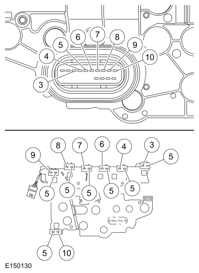
    Transmission internal wiring harness frame pin 5.

    Transmission internal wiring harness frame all pin fives.


Is the resistance less than 3 ohms?

Yes INSTALL a new PCM .
REFER to: Powertrain Control Module (PCM) (303-14B Electronic Engine Controls - 2.0L EcoBoost (184kW/250PS) - MI4, Removal and Installation).
PERFORM the Transmission Strategy Download, REFER to: Transmission Strategy Download (307-01B Automatic Transmission - Vehicles With: 6-Speed Automatic Transmission - 6F35, General Procedures).
No INSTALL a new transmission internal wiring harness frame.
REFER to: Transmission Internal Wiring Harness Frame (307-01B Automatic Transmission - Vehicles With: 6-Speed Automatic Transmission - 6F35, Removal and Installation).


Diagnostic Overview

Diagnostics in this manual assume a certain skill level and knowledge of Ford-specific diagnostic practices.
REFER to: Diagnostic Methods (100-00 General Information, Description and Operation).


Refer to Wiring Diagrams Cell 30 for schematic and connector information.

TFT Sensor

Normal Operation and Fault Conditions

The TFT sensor is located in the transmission internal wiring harness frame. The resistance value of the TFT sensor varies with temperature change. The PCM monitors the voltage drop across the TFT sensor to determine the temperature of the transmission fluid. When the ignition is turned to the run position, the PCM uses this initial input signal to determine whether a cold start shift schedule is necessary. The cold start shift schedule allows delayed shifts when the transmission fluid is cold. The PCM inhibits TCC operation at low transmission fluid temperatures and adjusts line pressure to temperature.


  DTC Fault Trigger Conditions


DTC Description Fault Trigger Conditions
P0710 Transmission Fluid Temperature Sensor "A" Circuit TFT sensor circuit shorted to ground or open.
P0711 Transmission Fluid Temperature Sensor "A" Circuit Range/Performance TFT sensor indicates a valid temperature but has not changed since start up.
P0712 Transmission Fluid Temperature Sensor "A" Circuit Low TFT sensor circuit short to ground.
P0713 Transmission Fluid Temperature Sensor "A" Circuit High TFT sensor circuit open.
P1711 Transmission Fluid Temperature Sensor Out Of Self Test Range TFT sensor indicates too hot or too cold and must indicate a normal temperature range during the KOER .
P1783 Transmission Overtemperature Condition TFT sensor indicates that the transmission is approaching an overheating condition.


Possible Sources


PINPOINT TEST G : TFT (TRANSMISSION FLUID TEMPERATURE) SENSOR
G1   RETRIEVE AND RECORD ALL DTCS
  • Using the diagnostic scan tool, retrieve all Diagnostic Trouble Codes (DTCs).

Are Diagnostic Trouble Codes (DTCs) P0710, P0711, P0712, P0713, P1711 and/or P1783 present?

Yes For Diagnostic Trouble Codes (DTCs) P0710, P0712 and/or P0713, GO to G2
For Diagnostic Trouble Codes (DTCs) P0711, P1711 and/or P1783, GO to G6
No
REFER to: Diagnosis By Symptom (307-01B Automatic Transmission - Vehicles With: 6-Speed Automatic Transmission - 6F35, Diagnosis and Testing).


G2   CHECK THE TFT (TRANSMISSION FLUID TEMPERATURE) SENSOR SIGNAL INPUT
  • Ignition OFF.
  • Disconnect Transmission Vehicle Harness C1520A .
  • Inspect the connectors for damaged or pushed-out terminals, corrosion, loose wires and missing or damaged seals.
  • Ignition ON.
  • Enter the following diagnostic mode: TFT and TFTV.

Does the TFT PID display a temperature -39.9 °F ( -40 °C) and the TFTV PID display 4.9 volts?

Yes GO to G5
No REPAIR the circuit.


G3   CHECK THE TFT (TRANSMISSION FLUID TEMPERATURE) SENSOR SIGNAL CIRCUIT
  • Connect.


    Positive Lead Measurement / Action Negative Lead
      C1520A-1   C1520A-2


Does the TFT PID display a temperature 375.5 °F ( 191 °C) and the TFTV PID display 0.0 to 0.2 volts?

Yes GO to G5
No GO to G4


G4   CHECK THE TFT (TRANSMISSION FLUID TEMPERATURE) SENSOR SIGNAL VOLTAGE
  • Measure.


    Positive Lead Measurement / Action Negative Lead
      C1520A-2   Ground


Is the voltage between 4.8 and 5.1 volts?

Yes GO to G5
No INSPECT and REPAIR the circuit. If an open circuit is not found, INSTALL a new PCM .
REFER to: Powertrain Control Module (PCM) (303-14B Electronic Engine Controls - 2.0L EcoBoost (184kW/250PS) - MI4, Removal and Installation).
PERFORM the Transmission Strategy Download, REFER to: Transmission Strategy Download (307-01B Automatic Transmission - Vehicles With: 6-Speed Automatic Transmission - 6F35, General Procedures).


G5   CHECK THE TFT (TRANSMISSION FLUID TEMPERATURE) SENSOR RESISTANCE
  • Measure.


    Positive Lead Measurement / Action Negative Lead

    Component side resistance pin 1.

    Component side resistance pin 2.


      Temperature


      °F ( °C) Ohms
    -39.9 –-4.0 °F ( -40 –-20 °C) 1,076K-269K
    -2.2 –30.2 °F ( -19 –-1 °C) 309K-91K
    32.0 –68.0 °F ( –20 °C) 104K-35K
    69.8 –103.9 °F ( 21 –40 °C) 40K-15K
    105.7 –157.9 °F ( 41 –70 °C) 17K-4.9K
    159.7 –193.9 °F ( 71 –90 °C) 5.6K-2.5K
    195.7 –229.8 °F ( 91 –110 °C) 3.0K-1.4K
    231.6 –265.8 °F ( 111 –130 °C) 1.7K-0.8K
    267.6 –301.8 °F ( 131 –150 °C) 0.97K-0.56K


Does the temperature to resistance specifications match?

Yes To diagnosis an overheating concern,
REFER to: Transmission Cooling (307-02B Transmission Cooling - Vehicles With: 6-Speed Automatic Transmission - 6F35, Diagnosis and Testing).
No INSTALL a new transmission internal wiring harness frame.
REFER to: Transmission Internal Wiring Harness Frame (307-01B Automatic Transmission - Vehicles With: 6-Speed Automatic Transmission - 6F35, Removal and Installation).


G6   ON DEMAND SELF-TEST
  • Check and make sure the transmission vehicle harness C1520A is fully seated, the terminals are engaged in the connector and in good condition before proceeding.
  • Using the diagnostic scan tool, make sure the transmission fluid temperature is between 33.8 °F ( 1 °C) and 219.1 °F ( 104 °C).
  • Perform the KOER self-test.

Did DTC P0711, P1711 and/or P1783 set?

Yes For Diagnostic Trouble Codes (DTCs) P0711 and P1711, INSTALL a new transmission internal wiring harness frame.
REFER to: Transmission Internal Wiring Harness Frame (307-01B Automatic Transmission - Vehicles With: 6-Speed Automatic Transmission - 6F35, Removal and Installation).
For DTC P1783,
REFER to: Transmission Cooling (307-02B Transmission Cooling - Vehicles With: 6-Speed Automatic Transmission - 6F35, Diagnosis and Testing).
No The system is operating correctly at this time. The concern may have been caused by a loose or corroded connector.


Diagnostic Overview

Diagnostics in this manual assume a certain skill level and knowledge of Ford-specific diagnostic practices.
REFER to: Diagnostic Methods (100-00 General Information, Description and Operation).


Refer to Wiring Diagrams Cell 30 for schematic and connector information.

TCC Solenoid

Normal Operation and Fault Conditions

The PCM controls torque converter lock-up by varying the amount of current applied to the TCC solenoid. When no current is applied to the TCC solenoid, the TCC is fully released. When maximum current is applied, the TCC is fully applied.

NOTE: Without a voltage signal return to the PCM , the transmission solenoid power control relay is commanded OFF. Using a fused jumper wire between a transmission solenoid control circuit and the signal return circuit, the transmission solenoid power control relay circuit supplies power to the transmission solenoids when the ignition is cycled from off to on. Do not use a solenoid control circuit that may be at fault, refer to DTC Charts for a fault listing.


  DTC Fault Trigger Conditions


DTC Description Fault Trigger Conditions
P0740 Torque Converter Clutch Solenoid Circuit/Open Open circuit in the TCC solenoid or wiring harness.
P0742 Torque Converter Clutch Solenoid Circuit Stuck On Short to ground in the TCC solenoid or wiring harness.
P0743 Torque Converter Clutch Solenoid Circuit Electrical Open or short to ground in the TCC solenoid or wiring harness.
P0744 Torque Converter Clutch Solenoid Circuit Intermittent Short to power in the TCC solenoid or wiring harness.
P2760 Torque Converter Clutch Pressure Control Solenoid Intermittent Intermittent circuit in the TCC solenoid or wiring harness. Open, short to ground or short to power.


Possible Sources


PINPOINT TEST H : TCC (TORQUE CONVERTER CLUTCH) SOLENOID
H1   RETRIEVE AND RECORD ALL DTCS
  • Using the diagnostic scan tool, retrieve all Diagnostic Trouble Codes (DTCs).

Are Diagnostic Trouble Codes (DTCs) P0740, P0742, P0743, P0744 and/or P2760 present?

Yes For Diagnostic Trouble Codes (DTCs) P0740, P0743 and P2760, GO to H2
For Diagnostic Trouble Codes (DTCs) P0742, P0743 and P2760, GO to H5
For Diagnostic Trouble Codes (DTCs) P0744, GO to H7
No
REFER to: Diagnosis By Symptom (307-01B Automatic Transmission - Vehicles With: 6-Speed Automatic Transmission - 6F35, Diagnosis and Testing).


H2   CHECK THE TCC (TORQUE CONVERTER CLUTCH) SOLENOID CONTROL CIRCUIT FOR AN OPEN
  • Ignition OFF.
  • Disconnect Transmission Vehicle Harness C1520A .
  • Disconnect PCM C1381E .
  • Inspect the connectors for damaged or pushed-out terminals, corrosion, loose wires and missing or damaged seals.
  • Measure.


    Positive Lead Measurement / Action Negative Lead
      C1520A-6   C1381E-44


Is the resistance less than 3 ohms?

Yes GO to H3
No REPAIR the circuit.


H3   CHECK THE TCC (TORQUE CONVERTER CLUTCH) SOLENOID CIRCUIT FOR AN OPEN
  • Measure.


    Positive Lead Measurement / Action Negative Lead

    Component side resistance pin 5.

    Component side resistance pin 6.


Is the resistance between 4.0 and 7.2 ohms?

Yes INSTALL a new PCM .
REFER to: Powertrain Control Module (PCM) (303-14B Electronic Engine Controls - 2.0L EcoBoost (184kW/250PS) - MI4, Removal and Installation).
PERFORM the Transmission Strategy Download, REFER to: Transmission Strategy Download (307-01B Automatic Transmission - Vehicles With: 6-Speed Automatic Transmission - 6F35, General Procedures).
No GO to H4


H4   CHECK THE TCC (TORQUE CONVERTER CLUTCH) SOLENOID RESISTANCE
  • Remove the transmission internal wiring harness frame.
    REFER to: Transmission Internal Wiring Harness Frame (307-01B Automatic Transmission - Vehicles With: 6-Speed Automatic Transmission - 6F35, Removal and Installation).
    Inspect for metal shavings on the exposed metal contacts or other components and clean the solenoid and transmission internal wiring harness frame terminals.
  • Measure.


    Positive Lead Measurement / Action Negative Lead

    TCC Solenoid pin A.

    TCC Solenoid pin B.


Is the resistance between 4.0 and 7.2 ohms?

Yes INSTALL a new transmission internal wiring harness frame.
REFER to: Transmission Internal Wiring Harness Frame (307-01B Automatic Transmission - Vehicles With: 6-Speed Automatic Transmission - 6F35, Removal and Installation).
No INSTALL a new TCC solenoid.
REFER to: Solenoid (307-01B Automatic Transmission - Vehicles With: 6-Speed Automatic Transmission - 6F35, Removal and Installation).


H5   CHECK THE TCC (TORQUE CONVERTER CLUTCH) SOLENOID CONTROL CIRCUIT FOR A SHORT TO GROUND
  • Ignition OFF.
  • Disconnect Transmission Vehicle Harness C1520A .
  • Disconnect PCM C1381E .
  • Inspect the connectors for damaged or pushed-out terminals, corrosion, loose wires and missing or damaged seals.
  • Measure.


    Positive Lead Measurement / Action Negative Lead
      C1520A-6   Ground


Is the resistance greater than 10,000 ohms?

Yes GO to H6
No REPAIR the circuit.


H6   CHECK THE TCC (TORQUE CONVERTER CLUTCH) SOLENOID FOR A SHORT TO GROUND
  • Remove the transmission internal wiring harness frame.
    REFER to: Transmission Internal Wiring Harness Frame (307-01B Automatic Transmission - Vehicles With: 6-Speed Automatic Transmission - 6F35, Removal and Installation).
    Inspect for metal shavings on the exposed metal contacts or other components and clean the solenoid and transmission internal wiring harness frame terminals.
  • Measure.


    Positive Lead Measurement / Action Negative Lead

    TCC Solenoid pin A.
      Ground


Is the resistance less than 3 ohms?

Yes INSTALL a new TCC solenoid.
REFER to: Solenoid (307-01B Automatic Transmission - Vehicles With: 6-Speed Automatic Transmission - 6F35, Removal and Installation).
No INSTALL a new transmission internal wiring harness frame.
REFER to: Transmission Internal Wiring Harness Frame (307-01B Automatic Transmission - Vehicles With: 6-Speed Automatic Transmission - 6F35, Removal and Installation).


H7   CHECK THE TCC (TORQUE CONVERTER CLUTCH) SOLENOID CONTROL CIRCUIT FOR A SHORT TO POWER
  • Ignition OFF.
  • Disconnect Transmission Vehicle Harness C1520A .
  • Disconnect PCM C1381E .
  • Inspect the connectors for damaged or pushed-out terminals, corrosion, loose wires and missing or damaged seals.
  • Ignition ON.
  • Measure.


    Positive Lead Measurement / Action Negative Lead
      C1520A-6   Ground


Is any voltage present?

Yes REPAIR the circuit.
No INSTALL a new PCM .
REFER to: Powertrain Control Module (PCM) (303-14B Electronic Engine Controls - 2.0L EcoBoost (184kW/250PS) - MI4, Removal and Installation).
PERFORM the Transmission Strategy Download, REFER to: Transmission Strategy Download (307-01B Automatic Transmission - Vehicles With: 6-Speed Automatic Transmission - 6F35, General Procedures).


Diagnostic Overview

Diagnostics in this manual assume a certain skill level and knowledge of Ford-specific diagnostic practices.
REFER to: Diagnostic Methods (100-00 General Information, Description and Operation).


Refer to Wiring Diagrams Cell 30 for schematic and connector information.

Pressure Control Solenoid A (PCA)

Normal Operation and Fault Conditions

The PCM controls the hydraulic line pressure by varying the amount of current applied to the Pressure Control Solenoid A (PCA), (Line Pressure Control (LPC) solenoid). When no current is applied to the Pressure Control Solenoid A (PCA), the Pressure Control Solenoid A (PCA) is fully opened, resulting in the maximum amount of hydraulic pressure to the main pressure regulator valve. When maximum current is applied, the Pressure Control Solenoid A (PCA) is fully closed, resulting in minimum pressure to the main pressure regulator valve.

NOTE: Without a voltage signal return to the PCM , the transmission solenoid power control relay is commanded OFF. Using a fused jumper wire between a transmission solenoid control circuit and the signal return circuit, the transmission solenoid power control relay circuit supplies power to the transmission solenoids when the ignition is cycled from off to on. Do not use a solenoid control circuit that may be at fault, refer to DTC Charts for a fault listing.


  DTC Fault Trigger Conditions


DTC Description Fault Trigger Conditions
P0748 Pressure Control Solenoid "A" Electrical Pressure control solenoid electrical circuit general fault. May set along with DTC P0960, P0962 and P0963.
P0960 Pressure Control Solenoid "A" Control Circuit/Open Open circuit in solenoid or solenoid circuitry.
P0961 Pressure Control Solenoid "A" Control Circuit Range/Performance Intermittent short to ground in solenoid or solenoid circuitry.
P0962 Pressure Control Solenoid "A" Control Circuit Low Short to ground in solenoid or solenoid circuitry.
P0963 Pressure Control Solenoid "A" Control Circuit High Short to power in solenoid circuitry.


Possible Sources


PINPOINT TEST I : PRESSURE CONTROL SOLENOID A (PCA)
I1   RETRIEVE AND RECORD ALL DTCS
  • Using the diagnostic scan tool, retrieve all Diagnostic Trouble Codes (DTCs).

Are Diagnostic Trouble Codes (DTCs) P0748, P0960, P0961, P0962 and/or P0963 present?

Yes For Diagnostic Trouble Codes (DTCs) P0748 and P0960, GO to I2
For Diagnostic Trouble Codes (DTCs) P0748, P0961 and P0962, GO to I5
For Diagnostic Trouble Codes (DTCs) P0748 and P0963, GO to I7
No
REFER to: Diagnosis By Symptom (307-01B Automatic Transmission - Vehicles With: 6-Speed Automatic Transmission - 6F35, Diagnosis and Testing).


I2   CHECK THE PRESSURE CONTROL SOLENOID A (PCA) CONTROL CIRCUIT FOR AN OPEN
  • Ignition OFF.
  • Disconnect Transmission Vehicle Harness C1520A .
  • Disconnect PCM C1381E .
  • Inspect the connectors for damaged or pushed-out terminals, corrosion, loose wires and missing or damaged seals.
  • Measure.


    Positive Lead Measurement / Action Negative Lead
      C1520A-3   C1381E-59


Is the resistance less than 3 ohms?

Yes GO to I3
No REPAIR the circuit.


I3   CHECK THE PRESSURE CONTROL SOLENOID A (PCA) FOR AN OPEN
  • Measure.


    Positive Lead Measurement / Action Negative Lead

    Component side resistance pin 5.

    Component side resistance pin 3.


Is the resistance between 4.0 and 7.2 ohms?

Yes INSTALL a new PCM .
REFER to: Powertrain Control Module (PCM) (303-14B Electronic Engine Controls - 2.0L EcoBoost (184kW/250PS) - MI4, Removal and Installation).
PERFORM the Transmission Strategy Download, REFER to: Transmission Strategy Download (307-01B Automatic Transmission - Vehicles With: 6-Speed Automatic Transmission - 6F35, General Procedures).
No GO to I4


I4   CHECK THE PRESSURE CONTROL SOLENOID A (PCA) RESISTANCE
  • Remove the transmission internal wiring harness frame.
    REFER to: Transmission Internal Wiring Harness Frame (307-01B Automatic Transmission - Vehicles With: 6-Speed Automatic Transmission - 6F35, Removal and Installation).
    Inspect for metal shavings on the exposed metal contacts or other components and clean the solenoid and transmission internal wiring harness frame terminals.
  • Measure.


    Positive Lead Measurement / Action Negative Lead

    Pressure Control Solenoid A (PCA) pin A.

    Pressure Control Solenoid A (PCA) pin B.


Is the resistance between 4.0 and 7.2 ohms?

Yes INSTALL a new transmission internal wiring harness frame.
REFER to: Transmission Internal Wiring Harness Frame (307-01B Automatic Transmission - Vehicles With: 6-Speed Automatic Transmission - 6F35, Removal and Installation).
No INSTALL a new Pressure Control Solenoid A (PCA).
REFER to: Solenoid (307-01B Automatic Transmission - Vehicles With: 6-Speed Automatic Transmission - 6F35, Removal and Installation).


I5   CHECK THE PRESSURE CONTROL SOLENOID A (PCA) CONTROL CIRCUIT FOR A SHORT TO GROUND
  • Ignition OFF.
  • Disconnect Transmission Vehicle Harness C1520A .
  • Disconnect PCM C1381E .
  • Inspect the connectors for damaged or pushed-out terminals, corrosion, loose wires and missing or damaged seals.
  • Measure.


    Positive Lead Measurement / Action Negative Lead
      C1520A-3   Ground


Is the resistance greater than 10,000 ohms?

Yes GO to I6
No REPAIR the circuit.


I6   CHECK THE PRESSURE CONTROL SOLENOID A (PCA) FOR A SHORT TO GROUND
  • Remove the transmission internal wiring harness frame.
    REFER to: Transmission Internal Wiring Harness Frame (307-01B Automatic Transmission - Vehicles With: 6-Speed Automatic Transmission - 6F35, Removal and Installation).
    Inspect for metal shavings on the exposed metal contacts or other components and clean the solenoid and transmission internal wiring harness frame terminals.
  • Measure.


    Positive Lead Measurement / Action Negative Lead

    Pressure Control Solenoid A (PCA) pin A.
      Ground


Is the resistance less than 3 ohms?

Yes INSTALL a new Pressure Control Solenoid A (PCA).
REFER to: Solenoid (307-01B Automatic Transmission - Vehicles With: 6-Speed Automatic Transmission - 6F35, Removal and Installation).
No INSTALL a new transmission internal wiring harness frame.
REFER to: Transmission Internal Wiring Harness Frame (307-01B Automatic Transmission - Vehicles With: 6-Speed Automatic Transmission - 6F35, Removal and Installation).


I7   CHECK THE PRESSURE CONTROL SOLENOID A (PCA) FOR A SHORT TO VOLTAGE
  • Ignition OFF.
  • Disconnect Transmission Vehicle Harness C1520A .
  • Disconnect PCM C1381E .
  • Inspect the connectors for damaged or pushed-out terminals, corrosion, loose wires and missing or damaged seals.
  • Ignition ON.
  • Measure.


    Positive Lead Measurement / Action Negative Lead
      C1520A-3   Ground


Is any voltage present?

Yes REPAIR the circuit.
No INSTALL a new PCM .
REFER to: Powertrain Control Module (PCM) (303-14B Electronic Engine Controls - 2.0L EcoBoost (184kW/250PS) - MI4, Removal and Installation).
PERFORM the Transmission Strategy Download, REFER to: Transmission Strategy Download (307-01B Automatic Transmission - Vehicles With: 6-Speed Automatic Transmission - 6F35, General Procedures).


Diagnostic Overview

Diagnostics in this manual assume a certain skill level and knowledge of Ford-specific diagnostic practices.
REFER to: Diagnostic Methods (100-00 General Information, Description and Operation).


Refer to Wiring Diagrams Cell 30 for schematic and connector information.

TR Sensor

Normal Operation and Fault Conditions

The TR sensor provides a fixed frequency duty cycle to the PCM for each manual control lever positions (PARK, REVERSE, NEUTRAL, DRIVE and LOW). The PCM uses the TR sensor signal for line pressure control, shift scheduling and TCC operation. The PCM transmits TR data on the HS-CAN to the BCM for engine start and reverse lamp operation.


  DTC Fault Trigger Conditions


DTC Description Fault Trigger Conditions
P0706 Transmission Range Sensor "A" Circuit Range/Performance Mechanical or electrical fault. Input from the TR sensor did not change or is intermittent.
P0707 Transmission Range Sensor "A" Circuit Low TR sensor circuit open or short to ground.
P0708 Transmission Range Sensor "A" Circuit High TR sensor circuit open.
P1702 Transmission Range Sensor "A" Circuit Intermittent TR sensor circuit open or short to ground.
P1705 Transmission Range Circuit Not Indicating Park/Neutral During Self Test TR sensor misaligned or in wrong position during the self-test.
P1921 Transmission Range Signal The PCM has detected a TR signal duty cycle out of range.


Possible Sources


PINPOINT TEST J : TR (TRANSMISSION RANGE) SENSOR
J1   RETRIEVE AND RECORD ALL DTCS
  • Using the diagnostic scan tool, retrieve all Diagnostic Trouble Codes (DTCs).

Are Diagnostic Trouble Codes (DTCs) P0706, P0707, P0708, P1702, P1705 and/or P1921 present?

Yes For Diagnostic Trouble Codes (DTCs) P0706, P0708, P1702 and/or P1921, GO to J2
For DTC P1705, GO to J9
No
REFER to: Diagnosis By Symptom (307-01B Automatic Transmission - Vehicles With: 6-Speed Automatic Transmission - 6F35, Diagnosis and Testing).


J2   VERIFY SELECTOR LEVER CABLE/LINKAGE ADJUSTMENT
  • Verify the selector lever cable/linkage is correctly adjusted,
    REFER to: Selector Lever Cable Adjustment (307-05B Automatic Transmission External Controls - Vehicles With: 6-Speed Automatic Transmission - 6F35, General Procedures).

Is the selector lever cable/linkage is correctly adjusted?

Yes GO to J3
No VERIFY the selector lever cable/ linkage adjustment,
REFER to: Selector Lever Cable Adjustment (307-05B Automatic Transmission External Controls - Vehicles With: 6-Speed Automatic Transmission - 6F35, General Procedures).
REPEAT the self-test. If the TR sensor Diagnostic Trouble Codes (DTCs) return, GO to J3


J3   CHECK THE TR (TRANSMISSION RANGE) SENSOR CIRCUITS FOR AN OPEN
  • Ignition OFF.
  • Disconnect Transmission Vehicle Harness C1520A .
  • Disconnect PCM C1381E .
  • Inspect the connectors for damaged or pushed-out terminals, corrosion, loose wires and missing or damaged seals.
  • Measure.


    Positive Lead Measurement / Action Negative Lead
      C1520A-17   C1381E-10
      C1520A-18   C1381E-22
      C1520A-20   C1381E-32


Is the resistance less than 3 ohms?

Yes GO to J4
No REPAIR the circuit.


J4   CHECK THE TR (TRANSMISSION RANGE) SENSOR CIRCUITS FOR A SHORT TO GROUND
  • Disconnect Transmission Vehicle Harness C1520B .
  • Inspect the connector for damaged or pushed-out terminals, corrosion, loose wires and missing or damaged seals.
  • Measure.


    Positive Lead Measurement / Action Negative Lead
      C1520A-17   Ground
      C1520A-18   Ground
      C1520A-20   Ground


Is the resistance greater than 10,000 ohms?

Yes GO to J5
No REPAIR the circuit.


J5   CHECK THE TR (TRANSMISSION RANGE) SENSOR CIRCUITS FOR A SHORT TO VOLTAGE
  • Ignition ON.
  • Measure.


    Positive Lead Measurement / Action Negative Lead
      C1520A-17   Ground
      C1520A-18   Ground
      C1520A-20   Ground


Is any voltage present?

Yes REPAIR the circuit.
No GO to J6


J6   CHECK THE TR (TRANSMISSION RANGE) SENSOR CIRCUITS FOR A SHORT TOGETHER
  • Ignition OFF.
  • Measure.


    Positive Lead Measurement / Action Negative Lead
      C1520A-20   C1520A-18
      C1520A-20   C1520A-17
      C1520A-18   C1520A-17


Yes GO to J7
No REPAIR the circuits.


J7   CHECK THE TR (TRANSMISSION RANGE) SENSOR CIRCUITS IN THE SOLENOID BODY LEADFRAME FOR AN OPEN
  • Remove the main control cover.
    REFER to: Main Control Cover (307-01B Automatic Transmission - Vehicles With: 6-Speed Automatic Transmission - 6F35, Removal and Installation).
  • Disconnect TR Sensor.
  • Inspect the connector for damaged or pushed-out terminals, corrosion, loose wires and missing or damaged seals.
  • Measure.


    Positive Lead Measurement / Action Negative Lead

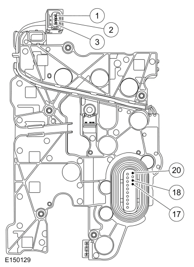
    Component side resistance pins 18, 17 and 20.

    Component side resistance pins 1, 2 and 3.


Is the resistance less than 3 ohms?

Yes GO to J8
No INSTALL a new transmission internal wiring harness frame.
REFER to: Transmission Internal Wiring Harness Frame (307-01B Automatic Transmission - Vehicles With: 6-Speed Automatic Transmission - 6F35, Removal and Installation).


J8   CHECK FOR VOLTAGE AND GROUND AT THE TR (TRANSMISSION RANGE) SENSOR
  • Connect PCM C1381E .
  • Connect Transmission Vehicle Harness C1520B .
  • Connect Transmission Vehicle Harness C1520A .
  • Ignition ON.
  • Measure.


    Positive Lead Measurement / Action Negative Lead

    TR sensor voltage supply pin 1.

    TR sensor ground pin 3.


Is the voltage greater than 10 volts?

Yes INSTALL a new TR sensor.
REFER to: Transmission Range (TR) Sensor (307-01B Automatic Transmission - Vehicles With: 6-Speed Automatic Transmission - 6F35, Removal and Installation).
No CHECK OASIS for applicable Technical Service Bulletins (TSBs). If a TSB exists for this concern, discontinue this test and follow the TSB instructions. If no Technical Service Bulletins (TSBs) address this concern, INSTALL a new PCM .
REFER to: Powertrain Control Module (PCM) (303-14B Electronic Engine Controls - 2.0L EcoBoost (184kW/250PS) - MI4, Removal and Installation).
PERFORM the Transmission Strategy Download, REFER to: Transmission Strategy Download (307-01B Automatic Transmission - Vehicles With: 6-Speed Automatic Transmission - 6F35, General Procedures).


J9   ON DEMAND SELF-TEST
  • Check to make sure the transmission harness connector is fully seated, terminals are engaged in connector and in good condition before proceeding.
  • Make sure the selector lever is in the Park or Neutral position.
  • Using the diagnostic scan tool, perform the KOEO self-test.

Did DTC P1705 return?

Yes VERIFY selector lever cable adjustment,
REFER to: Selector Lever Cable Adjustment (307-05B Automatic Transmission External Controls - Vehicles With: 6-Speed Automatic Transmission - 6F35, General Procedures).
No The system is operating correctly at this time. The concern may have been caused by a loose or corroded connector.


Diagnostic Overview

Diagnostics in this manual assume a certain skill level and knowledge of Ford-specific diagnostic practices.
REFER to: Diagnostic Methods (100-00 General Information, Description and Operation).


Refer to Wiring Diagrams Cell 30 for schematic and connector information.

TSS Sensor

Normal Operation and Fault Conditions

The TSS sensor is a Hall-effect sensor that sends a signal to the PCM that indicates transmission turbine shaft input speed. The TSS sensor provides converter turbine speed information for TCC strategy.


  DTC Fault Trigger Conditions


DTC Description Fault Trigger Conditions
P0715 Turbine/Input Shaft Speed Sensor "A" Circuit No input from the TSS sensor.
P0717 Turbine/Input Shaft Speed Sensor "A" Circuit No Signal No input from the TSS sensor.
P0718 Turbine/Input Shaft Speed Sensor "A" Circuit Intermittent Unrealistic change in the TSS sensor signal, erratic or intermittently no input.


Possible Sources


PINPOINT TEST K : TSS (TURBINE SHAFT SPEED) SENSOR
K1   RETRIEVE AND RECORD ALL DTCS
  • Using the diagnostic scan tool, retrieve all Diagnostic Trouble Codes (DTCs).

Are Diagnostic Trouble Codes (DTCs) P0715, P0717, P0718 and/or P0720 present?

Yes For Diagnostic Trouble Codes (DTCs) P0715, P0717 and P0718, GO to K2
For DTC P0715 and P0720, GO to K6
No
REFER to: Diagnosis By Symptom (307-01B Automatic Transmission - Vehicles With: 6-Speed Automatic Transmission - 6F35, Diagnosis and Testing).


K2   CHECK THE TSS (TURBINE SHAFT SPEED) SENSOR SIGNAL CIRCUIT FOR AN OPEN
  • Ignition OFF.
  • Disconnect Transmission Vehicle Harness C1520B .
  • Disconnect PCM C1381E .
  • Inspect the connectors for damaged or pushed-out terminals, corrosion, loose wires and missing or damaged seals.
  • Measure.


    Positive Lead Measurement / Action Negative Lead
      C1520B-2   C1381E-27


Is the resistance less than 3 ohms?

Yes GO to K3
No REPAIR the circuit.


K3   CHECK THE TSS (TURBINE SHAFT SPEED) SENSOR SIGNAL CIRCUIT FOR A SHORT TO GROUND
  • Measure.


    Positive Lead Measurement / Action Negative Lead
      C1520B-2   Ground


Is the resistance greater than 10,000 ohms?

Yes GO to K4
No REPAIR the circuit.


K4   CHECK THE TSS (TURBINE SHAFT SPEED) SENSOR SIGNAL CIRCUIT FOR A SHORT TO POWER
  • Ignition ON.
  • Measure.


    Positive Lead Measurement / Action Negative Lead
      C1520B-2   Ground


Is any voltage present?

Yes REPAIR the circuit.
No GO to K5


K5   CHECK THE TSS (TURBINE SHAFT SPEED) SENSOR GROUND CIRCUIT
  • Ignition OFF.
  • Connect PCM C1381E .
  • Ignition ON.
  • Measure.


    Positive Lead Measurement / Action Negative Lead
      C1520B-3   C1520B-1


Is voltage less than 4.8 volts?

Yes INSPECT and REPAIR the circuit. If an open circuit is not found, INSTALL a new PCM .
REFER to: Powertrain Control Module (PCM) (303-14B Electronic Engine Controls - 2.0L EcoBoost (184kW/250PS) - MI4, Removal and Installation).
PERFORM the Transmission Strategy Download, REFER to: Transmission Strategy Download (307-01B Automatic Transmission - Vehicles With: 6-Speed Automatic Transmission - 6F35, General Procedures).
No INSTALL a new TSS .
REFER to: Turbine Shaft Speed (TSS) Sensor (307-01B Automatic Transmission - Vehicles With: 6-Speed Automatic Transmission - 6F35, Removal and Installation).


K6   CHECK THE TSS (TURBINE SHAFT SPEED) SENSOR VEHICLE POWER CIRCUIT FOR AN OPEN
  • Ignition OFF.
  • Disconnect Transmission Vehicle Harness C1520B .
  • Inspect the connectors for damaged or pushed-out terminals, corrosion, loose wires and missing or damaged seals.
  • Ignition ON.
  • Measure.


    Positive Lead Measurement / Action Negative Lead
      C1520B-3   Ground


Is the voltage less than 9.5 volts?

Yes INSPECT and REPAIR the circuit. If an open circuit is not found, INSTALL a new PCM .
REFER to: Powertrain Control Module (PCM) (303-14B Electronic Engine Controls - 2.0L EcoBoost (184kW/250PS) - MI4, Removal and Installation).
PERFORM the Transmission Strategy Download, REFER to: Transmission Strategy Download (307-01B Automatic Transmission - Vehicles With: 6-Speed Automatic Transmission - 6F35, General Procedures).
No CLEAR the DTC . If Diagnostic Trouble Codes (DTCs) P0715 and/or P0720 return, INSTALL a new PCM .
REFER to: Powertrain Control Module (PCM) (303-14B Electronic Engine Controls - 2.0L EcoBoost (184kW/250PS) - MI4, Removal and Installation).
PERFORM the Transmission Strategy Download, REFER to: Transmission Strategy Download (307-01B Automatic Transmission - Vehicles With: 6-Speed Automatic Transmission - 6F35, General Procedures).


Diagnostic Overview

Diagnostics in this manual assume a certain skill level and knowledge of Ford-specific diagnostic practices.
REFER to: Diagnostic Methods (100-00 General Information, Description and Operation).


Refer to Wiring Diagrams Cell 30 for schematic and connector information.

OSS Sensor

Normal Operation and Fault Conditions

The OSS sensor is a Hall-effect sensor that sends a signal to the PCM that indicates transmission output shaft speed. The OSS sensor is used for TCC control and shift scheduling.


  DTC Fault Trigger Conditions


DTC Description Fault Trigger Conditions
P0720 Output Shaft Speed Sensor Circuit No input from the OSS sensor.
P0721 Output Shaft Speed Sensor Circuit Range/Performance Unrealistic change in the OSS sensor signal, erratic or intermittently no input.
P0722 Output Shaft Speed Sensor Circuit No Signal No input from the OSS sensor.


Possible Sources


PINPOINT TEST L : OSS (OUTPUT SHAFT SPEED) SENSOR
L1   RETRIEVE AND RECORD ALL DTCS
  • Using the diagnostic scan tool, retrieve all Diagnostic Trouble Codes (DTCs).

Are Diagnostic Trouble Codes (DTCs) P0720, P0721, P0722 and/or P0715, present?

Yes For Diagnostic Trouble Codes (DTCs) P0720, P0721 and P0722, GO to L2
For DTC P0715 and P0720, GO to L6
No
REFER to: Diagnosis By Symptom (307-01B Automatic Transmission - Vehicles With: 6-Speed Automatic Transmission - 6F35, Diagnosis and Testing).


L2   CHECK THE OSS (OUTPUT SHAFT SPEED) SENSOR SIGNAL CIRCUIT FOR AN OPEN
  • Ignition OFF.
  • Disconnect Transmission Vehicle Harness C1520A .
  • Disconnect PCM C1381E .
  • Inspect the connectors for damaged or pushed-out terminals, corrosion, loose wires and missing or damaged seals.
  • Measure.


    Positive Lead Measurement / Action Negative Lead
      C1520A-19   C1381E-12


Is the resistance less than 3 ohms?

Yes GO to L3
No REPAIR the circuit.


L3   CHECK THE OSS (OUTPUT SHAFT SPEED) SENSOR SIGNAL CIRCUIT FOR A SHORT TO GROUND
  • Measure.


    Positive Lead Measurement / Action Negative Lead
      C1520A-19   Ground


Is the resistance greater than 10,000 ohms?

Yes REPAIR the circuit.
No GO to L4


L4   CHECK THE OSS (OUTPUT SHAFT SPEED) SENSOR SIGNAL CIRCUIT FOR A SHORT TO POWER
  • Ignition ON.
  • Measure.


    Positive Lead Measurement / Action Negative Lead
      C1520A-19   Ground


Is any voltage present?

Yes REPAIR the circuit.
No GO to L5


L5   CHECK THE OSS (OUTPUT SHAFT SPEED) SENSOR GROUND CIRCUIT
  • Ignition OFF.
  • Connect PCM C1381E .
  • Ignition ON.
  • Measure.


    Positive Lead Measurement / Action Negative Lead
      C1520A-18   C1520A-20


Is voltage less than 4.8 volts?

Yes INSPECT and REPAIR the circuit. If an open circuit is not found, INSTALL a new PCM .
REFER to: Powertrain Control Module (PCM) (303-14B Electronic Engine Controls - 2.0L EcoBoost (184kW/250PS) - MI4, Removal and Installation).
PERFORM the Transmission Strategy Download, REFER to: Transmission Strategy Download (307-01B Automatic Transmission - Vehicles With: 6-Speed Automatic Transmission - 6F35, General Procedures).
No INSTALL a new OSS sensor.
REFER to: Output Shaft Speed (OSS) Sensor (307-01B Automatic Transmission - Vehicles With: 6-Speed Automatic Transmission - 6F35, Removal and Installation).


L6   CHECK THE OSS (OUTPUT SHAFT SPEED) SENSOR VEHICLE POWER CIRCUIT FOR AN OPEN
  • Ignition OFF.
  • Disconnect Transmission Vehicle Harness C1520A .
  • Inspect the connector for damaged or pushed-out terminals, corrosion, loose wires and missing or damaged seals.
  • Ignition ON.
  • Measure.


    Positive Lead Measurement / Action Negative Lead
      C1520A-18   Ground


Is voltage less than 9.5 volts?

Yes INSPECT and REPAIR the circuit. If an open circuit is not found, INSTALL a new PCM .
REFER to: Powertrain Control Module (PCM) (303-14B Electronic Engine Controls - 2.0L EcoBoost (184kW/250PS) - MI4, Removal and Installation).
PERFORM the Transmission Strategy Download, REFER to: Transmission Strategy Download (307-01B Automatic Transmission - Vehicles With: 6-Speed Automatic Transmission - 6F35, General Procedures).
No CLEAR the DTC . If Diagnostic Trouble Codes (DTCs) P0715 and/or P0720 return, INSTALL a new PCM .
REFER to: Powertrain Control Module (PCM) (303-14B Electronic Engine Controls - 2.0L EcoBoost (184kW/250PS) - MI4, Removal and Installation).
PERFORM the Transmission Strategy Download, REFER to: Transmission Strategy Download (307-01B Automatic Transmission - Vehicles With: 6-Speed Automatic Transmission - 6F35, General Procedures).