| 303-06A Starting System - 3.7L Duratec (227kW/301PS)
|
2013 - 2014 MKZ
|
| Diagnosis and Testing
|
Procedure revision date:
06/14/2013
|
Starting System
Inspection and Verification
Diagnostics in this manual assume a certain skill level and knowledge of Ford-specific diagnostic practices.
REFER to:
Diagnostic Methods
(100-00 General Information, Description and Operation).
-
Verify the customer concern by operating the starting system.
-
Check the battery condition and state of charge.
REFER to:
Battery
(414-01 Battery, Mounting and Cables, Diagnosis and Testing).
-
Remove the accessory drive belt.
REFER to:
Accessory Drive Belt
(303-05A Accessory Drive - 3.7L Duratec (227kW/301PS), Removal and Installation).
Verify the crankshaft and each of the components driven by the accessory drive belt rotate and are not seized or damaged.
-
If any aftermarket accessories have been added to the vehicle, make sure they are properly wired.
-
If an obvious cause for an observed or reported concern is found, correct the cause (if possible) before proceeding.
DTC Charts
Diagnostics in this manual assume a certain skill level and knowledge of Ford-specific diagnostic practices.
REFER to:
Diagnostic Methods
(100-00 General Information, Description and Operation).
PCM DTC Chart
|
DTC
|
Description
|
Action
|
|
PCM DTCs
|
PCM DTCs not listed in this chart
|
Refer to Powertrain Control/Emissions Diagnosis (PC/ED) manual.
|
|
P0512
|
Starter Request Circuit — Circuit has Power With the Ignition in the OFF Position
|
PERFORM the Ignition Switch Component Test. Refer to Wiring Diagrams Cell 149 for schematic and connector information. testing. If necessary, INSTALL a new ignition switch. If the ignition switch passed the component test, REPAIR circuit CDC35
(BU/WH) for a short to power.
|
|
P0616
|
Starter Relay "A" Circuit Low
|
GO to Pinpoint Test C
|
|
P0617
|
Starter Relay "A" Circuit High
|
GO to Pinpoint Test C
|
|
P06E9
|
Engine Starter Performance
|
If the engine cranks, Refer to Powertrain Control/Emissions Diagnosis (PC/ED) manual. If the engine does not crank,
GO to Pinpoint Test A
|
|
P0706
|
Transmission Range Sensor "A" Circuit Range/Performance
|
REFER to:
Automatic Transmission
(307-01A Automatic Transmission - Vehicles With: 6-Speed Automatic Transmission - 6F50, Diagnosis and Testing).
|
|
P0707
|
Transmission Range Sensor "A" Circuit Low
|
REFER to:
Automatic Transmission
(307-01A Automatic Transmission - Vehicles With: 6-Speed Automatic Transmission - 6F50, Diagnosis and Testing).
|
|
P0708
|
Transmission Range Sensor "A" Circuit High
|
REFER to:
Automatic Transmission
(307-01A Automatic Transmission - Vehicles With: 6-Speed Automatic Transmission - 6F50, Diagnosis and Testing).
|
|
P1260
|
Theft Detected, Vehicle Immobilized
|
REFER to:
Electronic Engine Controls
(303-14A Electronic Engine Controls - 3.7L Duratec (227kW/301PS), Diagnosis and Testing).
|
|
P1594
|
Forced engine shutdown – remote start system fault, No unattended vehicle timeout
|
GO to Pinpoint Test F
|
|
P1595
|
Forced engine shutdown - Remote Start System Fault, Transmission not in Park
|
GO to Pinpoint Test G
|
|
P162F
|
Starter Motor Disabled - Engine Crank Time Too Long
|
Refer to Powertrain Control/Emissions Diagnosis (PC/ED) manual.
|
|
P2533
|
Ignition Switch Run/Start Position Circuit
|
GO to Pinpoint Test E
|
|
P2534
|
Ignition Switch Run/Start Position Circuit Low
|
GO to Pinpoint Test E
|
|
P2535
|
Ignition Switch Run/Start Position Circuit High
|
GO to Pinpoint Test E
|
BCM DTC Chart
Symptom Chart(s)
Symptom Chart: Starting System
Diagnostics in this manual assume a certain skill level and knowledge of Ford-specific diagnostic practices.
REFER to:
Diagnostic Methods
(100-00 General Information, Description and Operation).
Symptom Chart
|
Condition
|
Possible Sources
|
Actions
|
|
The engine does not crank
|
Refer to the Pinpoint Test.
|
GO to Pinpoint Test A
|
|
The engine cranks slowly
|
Refer to the Pinpoint Test.
|
PERFORM the starter system component test. REFER to Starter Motor - Positive Circuit Test in this section.
|
|
The engine cranks but will not start
|
-
Fuses
-
-
Fuel pump
-
Fuel pump relay
-
Starter
-
Wiring
|
Refer to Powertrain Control/Emissions Diagnosis (PC/ED) manual.
|
|
Unusual starter noise
|
Refer to the Pinpoint Test.
|
GO to Pinpoint Test B
|
|
The starter spins but the engine does not crank
|
Starter motor
|
INSPECT the starter motor mounting and engagement. REPAIR as necessary.
|
|
Damaged flexplate
|
INSPECT the flexplate for damaged, missing or worn teeth. REPAIR as necessary.
|
|
The starter does not disengage from the flexplate
|
-
Starter relay
-
Wiring, terminals or connectors
|
REMOVE the starter relay. If the engine stops cranking, INSTALL a new relay. If the engine continues to crank, REPAIR circuit
CDC35 (BU/WH) for a short to voltage.
|
|
The remote start is inoperative
|
Possible Sources
-
Remote start feature not enabled
-
Passive Key
-
Hood switch input
-
-
Wiring, terminals or connectors
|
REFER to:
Locks, Latches and Entry Systems
(501-14 Handles, Locks, Latches and Entry Systems, Diagnosis and Testing).
|
|
The remote start has poor range performance
|
-
Passive Key or battery
-
After market systems
-
High power devices
-
TV/radio transmission towers
-
|
Diagnose The
Transmitter Has Poor Range Performance,
REFER to:
Locks, Latches and Entry Systems
(501-14 Handles, Locks, Latches and Entry Systems, Diagnosis and Testing).
|
Pinpoint Test(s)
Engine Does Not Crank
Refer to Wiring Diagrams Cell 20 for schematic and connector information.
Normal Operation and Fault Conditions
REFER to:
Starting System - Vehicles With: Keyless Entry and Push Button Start - System Operation and Component Description
(303-06A Starting System - 3.7L Duratec (227kW/301PS), Description and Operation).
DTC Fault Trigger Conditions
|
DTC
|
Description
|
Fault Trigger Conditions
|
|
P06E9
|
Engine Starter Performance
|
No engine rotation detected during crank event
|
Possible Sources
-
Battery
-
Battery cables
-
-
Starter motor
-
starter relay
Visual Inspection and Diagnostic Pre-checks
-
Inspect the Run/start relay.
-
Inspect the high current
connections.
-
Verify the
fuse 26 (10A).
-
Verify the
fuse 84 (30A).
-
Verify the
fuse 12 (7.5A).
-
Inspect the passive key.
PINPOINT TEST A : ENGINE DOES NOT CRANK
| A1
PERFORM INSPECTION AND VERIFICATION
|
-
Perform Inspection and Verification procedure in this section.
Was an obvious cause for an observed or reported concern found?
| Yes
|
CORRECT the cause as necessary.
|
|
| A2
CHECK FOR NO KEY DETECTED MESSAGE IN THE MESSAGE CENTER
|
-
NOTE:
There are certain areas inside the vehicle where the IA key may not be detected and the message center displays NO KEY DETECTED.
If the IA key is in the far outside edges of the interior (like in a door map pocket or above a sun visor) it might not be
detected. Move the IA key to a different location and try to start the vehicle again.
Check the message displayed in the message center while pressing the ignition switch - push button start.
Is NO KEY DETECTED displayed?
| Yes
|
DIAGNOSE the NO KEY DETECTED concern.
REFER to:
Perimeter Anti-Theft Alarm
(419-01A Perimeter Anti-Theft Alarm, Diagnosis and Testing).
|
|
| A3
VERIFY THE BCM (BODY CONTROL MODULE)
, IPC (INSTRUMENT PANEL CLUSTER)
AND PCM (POWERTRAIN CONTROL MODULE)
PASS THE NETWORK TEST
|
-
Using a diagnostic scan tool, perform the Network Test.
Did the
,
and
pass the Network Test?
|
| A4
RETRIEVE BCM (BODY CONTROL MODULE)
DTCS
|
-
Using a diagnostic scan tool, perform
self-test.
Are any Diagnostic Trouble Codes (DTCs) present?
| Yes
|
REFER to the BCM DTC Chart in this section.
|
|
| A5
RETRIEVE PCM (POWERTRAIN CONTROL MODULE)
DTCS
|
-
Using a diagnostic scan tool, perform
self-test.
Are any Diagnostic Trouble Codes (DTCs) present?
| Yes
|
For
P06E9 GO to
A6
For all other
Diagnostic Trouble Codes (DTCs), REFER to the PCM DTC Chart in this section.
|
|
| A6
CHECK THE OPERATION OF THE STOPLAMPS
|
-
While observing the stoplamps, apply the brake pedal.
Do the stoplamps illuminate?
| No
|
DIAGNOSE All the Stoplamps are Inoperative.
REFER to:
Stoplamps
(417-01 Exterior Lighting, Diagnosis and Testing).
|
|
| A7
CHECK THE BRAKE PEDAL POSITION (BOO1) PID (PARAMETER IDENTIFICATION)
|
-
Using a diagnostic scan tool, view
Parameter Identifications (PIDs).
-
Monitor the
B001
while applying the brake pedal.
Does the
read On?
|
| A8
CHECK THE BPP (BRAKE PEDAL POSITION)
SWITCH CIRCUIT FOR VOLTAGE AT THE PCM (POWERTRAIN CONTROL MODULE)
|
-
While applying the brake pedal, measure:
|
Positive Lead
|
Measurement / Action
|
Negative Lead
|
|
C175B-13
|

|
Ground
|
Is the voltage greater than 11 volts?
|
| A9
CHECK BCM (BODY CONTROL MODULE)
IGN_SW_STATE PID (PARAMETER IDENTIFICATION)
|
-
Using a diagnostic scan tool, view the
Parameter Identifications (PIDs).
-
Make sure the transmission is in PARK or NEUTRAL.
-
Monitor the
IGN_SW_STRT while pressing the ignition switch - push button start and the brake pedal.
Does the
change from Off to Start when the ignition switch - push button start and brake pedal are pressed?
|
| A10
CHECK THE PCM (POWERTRAIN CONTROL MODULE)
IN GEAR-TRANSMISSION IS APPLYING A LOAD TO ENGINE (IN_GEAR) PID (PARAMETER IDENTIFICATION)
|
-
Using a diagnostic scan tool, view the
Parameter Identifications (PIDs).
-
Monitor the
IN_GEAR, while placing the gear selector in PARK and then NEUTRAL.
Does the
read No in both positions?
| No
|
REFER to:
Automatic Transmission
(307-01A Automatic Transmission - Vehicles With: 6-Speed Automatic Transmission - 6F50, Diagnosis and Testing).
|
|
| A11
CHECK THE PCM (POWERTRAIN CONTROL MODULE)
ENGINE CRANKING (ENG_CRANK) PID (PARAMETER IDENTIFICATION)
|
-
Make sure the transmission is in PARK or NEUTRAL.
-
Using a diagnostic scan tool, view the
Parameter Identifications (PIDs).
-
Monitor the
ENG_CRANK while pressing the ignition switch - push button start and the brake pedal.
Does the
change from Inactive to Active?
|
| A12
CHECK THE STARTER RELAY CONTROL OPERATION
|
|
NOTICE:
The following step uses a test light to simulate normal circuit loads. Use only the test light recommended in the Special
Tools table at the beginning of this section. To avoid connector terminal damage, use the Flex Probe Kit for the test light
probe connection to the vehicle. Do not use the test light probe directly on any connector.
-
Remove the
starter relay.
-
Measure:
|
Positive Lead
|
Measurement / Action
|
Negative Lead
|
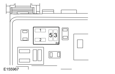 starter relay pin 1
|

|
starter relay pin 2
|
-
Make sure the transmission is in PARK or NEUTRAL.
-
While pressing the ignition switch - push button start and the brake pedal, observe the test light.
Does the test light illuminate when the ignition switch - push button start is pressed?
|
| A13
CHECK THE VOLTAGE TO THE STARTER RELAY
|
-
Measure:
|
Positive Lead
|
Measurement / Action
|
Negative Lead
|
|
starter relay pin 3
|
|
Ground
|
Is the voltage greater than 11 volts?
| No
|
VERIFY
fuse 84 (30A) is OK. If OK, REPAIR the circuit for an open. If not OK, REFER to the Wiring Diagrams manual to identify the
possible causes of the circuit short.
|
|
| A14
CHECK THE STARTER MOTOR OPERATION AT THE STARTER RELAY
|
-
With the transmission in PARK or NEUTRAL, momentarily connect a fused jumper wire:
|
Positive Lead
|
Measurement / Action
|
Negative Lead
|
|
starter relay pin 3
|

|
starter relay pin 5
|
Did the starter engage and the engine crank?
| Yes
|
INSTALL a new starter relay.
|
|
| A15
CHECK THE BATTERY GROUND CABLES
|
-
Measure:
|
Positive Lead
|
Measurement / Action
|
Negative Lead
|
|
|
Ground G108
|
|
|
|
Ground G109
|
Are the voltages greater than 11 volts?
|
| A16
CHECK THE STARTER MOTOR GROUND
|
Is the voltage greater than 11 volts?
| No
|
CLEAN the starter motor mounting flange and MAKE SURE the starter motor is correctly mounted.
REFER to:
Starter Motor
(303-06A Starting System - 3.7L Duratec (227kW/301PS), Removal and Installation).
|
|
| A17
CHECK THE VOLTAGE TO THE STARTER MOTOR
|
-
Measure:
|
Positive Lead
|
Measurement / Action
|
Negative Lead
|
|
C1715A-1 ("B" terminal)
|
|
Ground
|
Is the voltage greater than 11 volts?
|
| A18
CHECK THE STARTER MOTOR FOR CORRECT OPERATION
|
-
Perform Starter Motor - Positive Circuit Test in this section.
Was an obvious cause found?
| Yes
|
Correct the cause as necessary.
|
|
| A19
CHECK FOR START INPUT AT THE STARTER
|
-
Disconnect Starter solenoid C1715B
.
-
While holding the key in the START position, measure:
|
Positive Lead
|
Measurement / Action
|
Negative Lead
|
|
C1715B-1 ("S" terminal)
|
|
Ground
|
Is the voltage greater than 11 volts?
| Yes
|
CLEAN the starter solenoid "S" terminal and starter solenoid connector. CHECK the wiring and the starter motor for a loose
or intermittent connection.
|
| No
|
REPAIR the circuit for an open.
|
|
| A20
CHECK THE PCM (POWERTRAIN CONTROL MODULE)
STARTER RELAY CONTROL (-) CIRCUIT FOR A SHORT TO GROUND
|
-
Measure:
|
Positive Lead
|
Measurement / Action
|
Negative Lead
|
|
C175B-7
|

|
Ground
|
Are the resistances greater than 10,000 ohms?
| No
|
REPAIR the affected circuit.
|
|
| A21
CHECK THE PCM (POWERTRAIN CONTROL MODULE)
STARTER RELAY CONTROL (+) CIRCUIT FOR A SHORT TO GROUND
|
-
Measure:
|
Positive Lead
|
Measurement / Action
|
Negative Lead
|
|
C175B-37
|
|
Ground
|
Are the resistances greater than 10,000 ohms?
| No
|
For vehicles without THX GO to
A22
For vehicles with THX, REPAIR the affected circuit.
|
|
| A22
CHECK THE ACM (AUDIO FRONT CONTROL MODULE)
STARTER CIRCUIT FOR A SHORT TO GROUND
|
-
Measure:
|
Positive Lead
|
Measurement / Action
|
Negative Lead
|
|
C175B-37
|
|
Ground
|
Are the resistances greater than 10,000 ohms?
| Yes
|
REPLACE the
,
REFER to:
Audio Front Control Module (ACM)
(415-00A Information and Entertainment System - General Information - Vehicles With: Touchscreen Display, Removal and Installation).
|
| No
|
REPAIR the affected circuit.
|
|
| A23
CHECK THE PCM (POWERTRAIN CONTROL MODULE)
STARTER RELAY CONTROL CIRCUITS FOR OPENS
|
Are the resistances less than 3 ohms?
| No
|
REPAIR the affected circuit.
|
|
| A24
CHECK FOR CORRECT PCM (POWERTRAIN CONTROL MODULE)
OPERATION
|
-
Disconnect and inspect all
connectors.
-
Repair:
-
corrosion (install new connectors or terminals - clean module pins)
-
damaged or bent pins - install new terminals/pins
-
pushed-out pins - install new pins as necessary
-
Reconnect the
connectors. Make sure they seat and latch correctly.
-
Operate the system and determine if the concern is still present.
Is the concern still present?
| Yes
|
CHECK
for any applicable Technical Service Bulletins (TSBs). If a
exists for this concern, DISCONTINUE this test and FOLLOW the
instructions. If no Technical Service Bulletins (TSBs) address this concern, INSTALL a new
.
REFER to:
Electronic Engine Controls
(303-14A Electronic Engine Controls - 3.7L Duratec (227kW/301PS), Diagnosis and Testing).
|
| No
|
The system is operating correctly at this time. The concern may have been caused by module connections. ADDRESS the root cause
of any connector or pin issues.
|
|
Unusual Starter Noise
Normal Operation and Fault Conditions
Correct starter operation relies on correct mounting of the starter to the engine, alignment of the starter ring gear to the
flexplate and correct functioning of the starter assembly (internal gears, bearings).
Possible Sources
-
Engine
-
Starter motor
-
Starter motor mounting
Visual Inspection and Diagnostic Pre-checks
-
Inspect the starter motor.
-
Inspect the starter motor mounting.
PINPOINT TEST B : UNUSUAL STARTER NOISE
| B1
CHECK THE STARTER MOUNTING
|
-
Inspect the starter mounting bolts for looseness.
Is the starter motor mounted correctly?
| No
|
INSTALL the starter motor correctly.
REFER to:
Starter Motor
(303-06A Starting System - 3.7L Duratec (227kW/301PS), Removal and Installation).
|
|
| B2
CHECK FOR STARTER NOISE
|
-
Connect a remote starter switch between the starter solenoid C1715A-1 ("B" terminal) and C1715B-1 ("S" terminal).
-
Engage the starter and verify the noise is due to starter operation.
Is the noise due to the starter engagement?
| No
|
REFER to:
Engine
(303-00 Engine System - General Information, Diagnosis and Testing).
to continue diagnosis.
|
|
P0616 or P0617
Refer to Wiring Diagrams Cell 20 for schematic and connector information.
Normal Operation and Fault Conditions
REFER to:
Starting System - Vehicles With: Keyless Entry and Push Button Start - System Operation and Component Description
(303-06A Starting System - 3.7L Duratec (227kW/301PS), Description and Operation).
DTC Fault Trigger Conditions
|
DTC
|
Description
|
Fault Trigger Conditions
|
|
P0616
|
Starter Relay "A" Circuit Low
|
This
is set when the
detects a short to ground in the starter relay control circuit(s).
|
|
P0617
|
Starter Relay "A" Circuit High
|
This
is set when the
detects an open, or short to power in the starter relay control circuit(s).
|
Possible Sources
-
-
Wiring, terminals or connectors
Visual Inspection and Diagnostic Pre-checks
-
Verify the
fuse 84 (30A).
PINPOINT TEST C : P0616 OR P0617
| C1
CHECK THE PCM (POWERTRAIN CONTROL MODULE)
STARTER RELAY CIRCUITS FOR A SHORT TO VOLTAGE
|
-
Disconnect
starter relay.
-
Measure:
|
Positive Lead
|
Measurement / Action
|
Negative Lead
|
|
C175B-7
|
|
Ground
|
|
C175B-37
|
|
Ground
|
Is any voltage present?
| Yes
|
REPAIR the affected circuit.
|
|
| C2
CHECK THE PCM (POWERTRAIN CONTROL MODULE)
STARTER RELAY CIRCUITS FOR A SHORT TO GROUND
|
-
Measure:
|
Positive Lead
|
Measurement / Action
|
Negative Lead
|
|
C175B-7
|
|
Ground
|
|
C175B-37
|
|
Ground
|
Are the resistances greater than 10,000 ohms?
| No
|
REPAIR the affected circuit.
|
|
| C3
CHECK THE PCM (POWERTRAIN CONTROL MODULE)
STARTER RELAY CIRCUITS FOR AN OPEN
|
Are the resistances less than 3 ohms?
| No
|
REPAIR the affected circuit.
|
|
| C4
CHECK BJB (BATTERY JUNCTION BOX)
STARTER RELAY
|
-
Replace
starter relay with a known good relay.
-
Using a diagnostic scan tool, perform the
self-test.
Is
Diagnostic Trouble Code (DTC) P0616 or P0617 still present?
| No
|
INSTALL a new
starter relay.
|
|
| C5
CHECK FOR CORRECT PCM (POWERTRAIN CONTROL MODULE)
OPERATION
|
-
Disconnect and inspect all
connectors.
-
Repair:
-
corrosion (install new connectors or terminals - clean module pins)
-
damaged or bent pins - install new terminals/pins
-
pushed-out pins - install new pins as necessary
-
Reconnect the
connectors. Make sure they seat and latch correctly.
-
Operate the system and determine if the concern is still present.
Is the concern still present?
| Yes
|
CHECK
for any applicable Technical Service Bulletins (TSBs). If a
exists for this concern, DISCONTINUE this test and FOLLOW the
instructions. If no Technical Service Bulletins (TSBs) address this concern, INSTALL a new
.
REFER to:
Powertrain Control Module (PCM)
(303-14A Electronic Engine Controls - 3.7L Duratec (227kW/301PS), Removal and Installation).
|
| No
|
The system is operating correctly at this time. The concern may have been caused by module connections. ADDRESS the root cause
of any connector or pin issues.
|
|
C113A:11 or C113A:15
Refer to Wiring Diagrams Cell 23 for schematic and connector information.
Normal Operation and Fault Conditions
The wake-up control circuit wakes up the
prior to the engine cranking. The
needs to wake up prior to a crank request so it has time to go through its initialization. The wake-up control circuit is
controlled by the
. The
activates the wake-up control circuit when the driver door is opened or when the ignition is in the ON or START position.
DTC Fault Trigger Conditions
|
DTC
|
Description
|
Fault Trigger Conditions
|
|
C113A:11
|
Wake-up Signal: Circuit Short to Ground
|
Set by the
when a short to ground is detected on the wake-up control circuit.
|
|
C113A:15
|
Wake-up Signal: Circuit Short to Battery or Open
|
Set by the
when a short to voltage or an open is detected on the wake-up control circuit.
|
Possible Sources
-
-
-
Wiring, terminals or connectors
PINPOINT TEST D : C113A:11 OR C113A:15
| D1
CHECK FOR BCM (BODY CONTROL MODULE)
DTCS
|
-
Using a diagnostic scan tool, perform the
self-test.
Is
C113A:11 present?
| No
|
If
C113A:15 is present, GO to
D4
For all other
Diagnostic Trouble Codes (DTCs),
REFER to:
Body Control Module (BCM)
(419-10 Multifunction Electronic Modules, Diagnosis and Testing).
|
|
| D2
CHECK THE PCM (POWERTRAIN CONTROL MODULE)
FOR A SHORT TO GROUND
|
-
Using a diagnostic scan tool, clear the
Diagnostic Trouble Codes (DTCs).
-
Using a diagnostic scan tool, perform the
self-test.
Is
C113A:11 present?
|
| D3
CHECK THE PCM (POWERTRAIN CONTROL MODULE)
WAKE-UP SIGNAL CIRCUIT FOR A SHORT TO GROUND
|
-
Measure:
|
Positive Lead
|
Measurement / Action
|
Negative Lead
|
|
C175B-28
|
|
Ground
|
Is the resistance greater than 10,000 ohms?
|
| D4
CHECK THE PCM (POWERTRAIN CONTROL MODULE)
WAKE-UP SIGNAL CIRCUIT FOR A SHORT TO VOLTAGE
|
-
Disconnect
C175B if necessary.
-
Measure:
|
Positive Lead
|
Measurement / Action
|
Negative Lead
|
|
C175B-35
|
|
Ground
|
Is any voltage present?
|
| D5
CHECK THE PCM (POWERTRAIN CONTROL MODULE)
WAKE-UP SIGNAL CIRCUIT FOR AN OPEN
|
-
Measure:
|
Positive Lead
|
Measurement / Action
|
Negative Lead
|
|
C175B-35
|
|
C2280C-18
|
Is the resistance less than 3 ohms?
|
| D6
CHECK FOR CORRECT BCM (BODY CONTROL MODULE)
OPERATION
|
-
Disconnect and inspect all
connectors.
-
Repair:
-
corrosion (install new connectors or terminals - clean module pins)
-
damaged or bent pins - install new terminals/pins
-
pushed-out pins - install new pins as necessary
-
Reconnect the
connectors. Make sure they seat and latch correctly.
-
Operate the system and determine if the concern is still present.
Is the concern still present?
| Yes
|
CHECK
for any applicable Technical Service Bulletins (TSBs). If a
exists for this concern, DISCONTINUE this test and FOLLOW the
instructions. If no Technical Service Bulletins (TSBs) address this concern, INSTALL a new
.
REFER to:
Body Control Module (BCM)
(419-10 Multifunction Electronic Modules, Removal and Installation).
|
| No
|
The system is operating correctly at this time. The concern may have been caused by module connections. ADDRESS the root cause
of any connector or pin issues.
|
|
| D7
CHECK FOR CORRECT PCM (POWERTRAIN CONTROL MODULE)
OPERATION
|
-
Disconnect and inspect all
connectors.
-
Repair:
-
corrosion (install new connectors or terminals - clean module pins)
-
damaged or bent pins - install new terminals/pins
-
pushed-out pins - install new pins as necessary
-
Reconnect the
connectors. Make sure they seat and latch correctly.
-
Operate the system and determine if the concern is still present.
Is the concern still present?
| Yes
|
CHECK
for any applicable Technical Service Bulletins (TSBs). If a
exists for this concern, DISCONTINUE this test and FOLLOW the
instructions. If no Technical Service Bulletins (TSBs) address this concern, INSTALL a new
.
REFER to:
Powertrain Control Module (PCM)
(303-14A Electronic Engine Controls - 3.7L Duratec (227kW/301PS), Removal and Installation).
|
| No
|
The system is operating correctly at this time. The concern may have been caused by module connections. ADDRESS the root cause
of any connector or pin issues.
|
|
P2533, P2534, or P2535
Refer to Wiring Diagrams Cell 20 for schematic and connector information.
Normal Operation and Fault Conditions
When the ignition switch - push button start has been pressed, the
receives a voltage signal on the crank detect circuit. When the required inputs have been received, the
supplies voltage and ground to the starter relay coil. The ignition switch - push button start is part of the gear shift
module and cannot be serviced separately. For more information,
REFER to:
Starting System - Vehicles With: Keyless Entry and Push Button Start - System Operation and Component Description
(303-06A Starting System - 3.7L Duratec (227kW/301PS), Description and Operation).
DTC Fault Trigger Conditions
|
DTC
|
Description
|
Fault Trigger Conditions
|
|
P2533
|
Ignition Switch Run/Start Position Circuit
|
This
is set when the
detects a fault on the crank detect circuit.
|
|
P2534
|
Ignition Switch Run/Start Position Circuit Low
|
This
is set when the
detects a short to ground on the crank detect circuit. The fault condition is observed as no power in any ignition mode due
to
fuse 12 (7.5A) opening after the ignition switch - push button start is pressed.
|
|
P2535
|
Ignition Switch Run/Start Position Circuit High
|
This
is set when the
detects a short to voltage on the crank detect circuit while engine is running.
|
Possible Sources
-
Ignition switch - push button start
-
-
-
Wiring, terminals or connectors
Visual Inspection and Diagnostic Pre-checks
-
Verify the
fuse 12 (7.5A).
PINPOINT TEST E : P2533, P2534, OR P2535
| E1
CHECK FOR PCM (POWERTRAIN CONTROL MODULE)
DTCS
|
-
Using a diagnostic scan tool, perform the
self-test.
Is
Diagnostic Trouble Code (DTC) P2534 present?
| No
|
For
P2533 or P2535, GO to
E2
For all other
Diagnostic Trouble Codes (DTCs), REFER to PCM DTC Chart in this section.
|
|
| E2
CHECK THE CRANK DETECT CIRCUIT FOR A SHORT TO VOLTAGE WITH THE PCM (POWERTRAIN CONTROL MODULE)
DISCONNECTED
|
-
Measure:
|
Positive Lead
|
Measurement / Action
|
Negative Lead
|
|
C175B-16
|
|
Ground
|
Is any voltage present?
|
| E3
CHECK THE CRANK DETECT CIRCUIT FOR A SHORT TO VOLTAGE WITH THE IGNITION SWITCH - PUSH BUTTON START DISCONNECTED
|
-
Disconnect Ignition switch - push button start C3532
.
-
Measure:
|
Positive Lead
|
Measurement / Action
|
Negative Lead
|
|
C175B-16
|
|
Ground
|
Is any voltage present?
| No
|
Install a new ignition switch - push button start.
REFER to:
Gearshift Module (GSM)
(307-05A Automatic Transmission External Controls - Vehicles With: 6-Speed Automatic Transmission - 6F50, Removal and Installation).
|
|
| E4
CHECK THE CRANK DETECT CIRCUIT FOR A SHORT TO VOLTAGE WITH THE BCM (BODY CONTROL MODULE)
DISCONNECTED
|
-
Measure:
|
Positive Lead
|
Measurement / Action
|
Negative Lead
|
|
C175B-16
|
|
Ground
|
Is any voltage present?
|
| E5
CHECK THE CRANK DETECT CIRCUIT FOR A SHORT TO GROUND WITH THE PCM (POWERTRAIN CONTROL MODULE)
DISCONNECTED
|
-
Measure:
|
Positive Lead
|
Measurement / Action
|
Negative Lead
|
|
C175B-16
|
|
Ground
|
Is the resistance greater than 10,000 ohms?
|
| E6
CHECK THE CRANK DETECT CIRCUIT FOR A SHORT TO GROUND WITH THE IGNITION SWITCH - PUSH BUTTON START DISCONNECTED
|
-
Disconnect Gear shift module C3532
.
-
Measure:
|
Positive Lead
|
Measurement / Action
|
Negative Lead
|
|
C175B-16
|
|
Ground
|
Is the resistance greater than 10,000 ohms?
| Yes
|
Install a new ignition switch - push button start.
REFER to:
Gearshift Module (GSM)
(307-05A Automatic Transmission External Controls - Vehicles With: 6-Speed Automatic Transmission - 6F50, Removal and Installation).
|
|
| E7
CHECK THE CRANK DETECT CIRCUIT FOR A SHORT TO GROUND WITH THE BCM (BODY CONTROL MODULE)
DISCONNECTED
|
-
Measure:
|
Positive Lead
|
Measurement / Action
|
Negative Lead
|
|
C175B-16
|
|
Ground
|
Is the resistance greater than 10,000 ohms?
|
| E8
CHECK THE CRANK DETECT CIRCUIT TO PCM (POWERTRAIN CONTROL MODULE)
FOR AN OPEN
|
-
Measure:
|
Positive Lead
|
Measurement / Action
|
Negative Lead
|
|
C3532-7
|
|
C175B-16
|
Is the resistance less than 3 ohms?
|
| E9
CHECK THE CRANK DETECT CIRCUIT TO BCM (BODY CONTROL MODULE)
FOR AN OPEN
|
-
Measure:
|
Positive Lead
|
Measurement / Action
|
Negative Lead
|
|
C3532-7
|
|
C2280G-51
|
Is the resistance less than 3 ohms?
|
| E10
CHECK FOR CORRECT PCM (POWERTRAIN CONTROL MODULE)
OPERATION
|
-
Disconnect and inspect all
connectors.
-
Repair:
-
corrosion (install new connectors or terminals - clean module pins)
-
damaged or bent pins - install new terminals/pins
-
pushed-out pins - install new pins as necessary
-
Reconnect the
connectors. Make sure they seat and latch correctly.
-
Operate the system and determine if the concern is still present.
Is the concern still present?
| Yes
|
CHECK
for any applicable Technical Service Bulletins (TSBs). If a
exists for this concern, DISCONTINUE this test and FOLLOW the
instructions. If no Technical Service Bulletins (TSBs) address this concern, INSTALL a new
.
REFER to:
Powertrain Control Module (PCM)
(303-14A Electronic Engine Controls - 3.7L Duratec (227kW/301PS), Removal and Installation).
|
| No
|
The system is operating correctly at this time. The concern may have been caused by module connections. ADDRESS the root cause
of any connector or pin issues.
|
|
P1594
Refer to Wiring Diagrams Cell 20 for schematic and connector information.
Normal Operation and Fault Conditions
The remote start system runs the engine for 10 minutes (the time can be programmed by the customer to 5, 10 or 15 minutes).
This
sets when the
detects that the
did not shut down the engine before 35 minutes of run time. For more information,
REFER to:
Starting System - Vehicles With: Keyless Entry and Push Button Start - System Operation and Component Description
(303-06A Starting System - 3.7L Duratec (227kW/301PS), Description and Operation).
DTC Fault Trigger Conditions
|
DTC
|
Description
|
Fault Trigger Conditions
|
|
P1594
|
Forced engine shutdown – remote start system fault, No unattended vehicle timeout
|
This
sets when the
detects that the
did not shut down the engine before 35 minutes of run time.
|
Possible Sources
-
Network communication error
-
-
Wiring, terminals or connectors
PINPOINT TEST F : P1594
| F1
VERIFY THE BCM (BODY CONTROL MODULE)
AND PCM (POWERTRAIN CONTROL MODULE)
PASS THE NETWORK TEST
|
-
Using a diagnostic scan tool, perform the Network Test.
Did the
and
pass the Network Test?
|
| F2
CHECK FOR CORRECT BCM (BODY CONTROL MODULE)
OPERATION
|
-
Disconnect and inspect all
connectors.
-
Repair:
-
corrosion (install new connectors or terminals - clean module pins)
-
damaged or bent pins - install new terminals/pins
-
pushed-out pins - install new pins as necessary
-
Reconnect the
connectors. Make sure they seat and latch correctly.
-
Operate the system and determine if the concern is still present.
Is the concern still present?
| Yes
|
CHECK
for any applicable Technical Service Bulletins (TSBs). If a
exists for this concern, DISCONTINUE this test and FOLLOW the
instructions. If no Technical Service Bulletins (TSBs) address this concern, INSTALL a new
.
REFER to:
Body Control Module (BCM)
(419-10 Multifunction Electronic Modules, Removal and Installation).
|
| No
|
The system is operating correctly at this time. The concern may have been caused by module connections. ADDRESS the root cause
of any connector or pin issues.
|
|
P1595
Refer to Wiring Diagrams Cell 20 for schematic and connector information.
Normal Operation and Fault Conditions
The selector lever must be in Park for the remote start to engage. If the
detects that the transmission as transitioned out of park during a remote start event
P1595 sets. P1595 also sets if the
receives a
message that the
is in drive mode and the
does not receive an in gear message from the automatic transmission.
DTC Fault Trigger Conditions
|
DTC
|
Description
|
Fault Trigger Conditions
|
|
P1595
|
Forced engine shutdown - Remote Start System Fault, Transmission not in Park
|
This
sets when the
is in non-motive mode and detects that the selector lever has moved from Park.
|
Possible Sources
-
Brake Shift Interlock Actuator (BSIA)
-
-
Selector lever worn or loose
-
Selector lever cable brackets loose
-
-
-
Wiring, terminals or connectors
Visual Inspection and Diagnostic Pre-checks
-
Inspect Selector lever for looseness.
PINPOINT TEST G : P1595
| G1
CHECK PARK LOCK OPERATION
|
-
NOTE:
Do not press the brake pedal.
Try to move selector lever from Park to Reverse position.
Will the selector lever move from Park to Reverse?
| Yes
|
REFER to:
External Controls
(307-05A Automatic Transmission External Controls - Vehicles With: 6-Speed Automatic Transmission - 6F50, Diagnosis and Testing).
|
|
| G2
CHECK BCM (BODY CONTROL MODULE)
FOR DIAGNOSTIC TROUBLE CODES (DTCS)
|
-
Using a diagnostic scan tool, perform the BCM self-test.
Is
DTC B1319:11 or B1319:15 present?
| Yes
|
REFER to:
External Controls
(307-05A Automatic Transmission External Controls - Vehicles With: 6-Speed Automatic Transmission - 6F50, Diagnosis and Testing).
|
|
| G3
CHECK SELECTOR LEVER FOR PARK POSITION
|
-
Using a diagnostic scan tool, view
Parameter Identifications (PIDs).
Does the
read Yes?
| No
|
Adjust selector lever cable and retest.
REFER to:
Selector Lever Cable Adjustment
(307-05A Automatic Transmission External Controls - Vehicles With: 6-Speed Automatic Transmission - 6F50, General Procedures).
If the
still reads Yes replace the selector lever.
|
|
| G4
CHECK PCM IN_GEAR PID (PARAMETER IDENTIFICATION)
|
-
NOTE:
Do not press the brake pedal.
While viewing the
In_Gear try to move selector lever from Park to Reverse position several times.
Does the
change from No to Yes?
| Yes
|
REFER to:
External Controls
(307-05A Automatic Transmission External Controls - Vehicles With: 6-Speed Automatic Transmission - 6F50, Diagnosis and Testing).
|
|
| G5
CHECK PARK NEUTRAL POSITION SWITCH
|
-
Press and hold the brake pedal.
-
While viewing the
In_Gear move selector lever from Park to Reverse.
Does the
change from No to Yes?
| No
|
DIAGNOSE the
switch.
REFER to:
Automatic Transmission
(307-01A Automatic Transmission - Vehicles With: 6-Speed Automatic Transmission - 6F50, Diagnosis and Testing).
|
|
| G6
CHECK FOR CORRECT BCM (BODY CONTROL MODULE)
OPERATION
|
-
Disconnect and inspect all
connectors.
-
Repair:
-
corrosion (install new connectors or terminals - clean module pins)
-
damaged or bent pins - install new terminals/pins
-
pushed-out pins - install new pins as necessary
-
Reconnect the
connectors. Make sure they seat and latch correctly.
-
Operate the system and determine if the concern is still present.
Is the concern still present?
| Yes
|
CHECK
for any applicable Technical Service Bulletins (TSBs). If a
exists for this concern, DISCONTINUE this test and FOLLOW the
instructions. If no Technical Service Bulletins (TSBs) address this concern, INSTALL a new
.
REFER to:
Body Control Module (BCM)
(419-10 Multifunction Electronic Modules, Removal and Installation).
|
| No
|
The system is operating correctly at this time. The concern may have been caused by module connections. ADDRESS the root cause
of any connector or pin issues.
|
|
Component Test(s)
Starter Motor - Positive Circuit Test
 WARNING:
Before beginning any service procedure in this section, refer to Safety Warnings in section 100-00 General Information. Failure
to follow this instruction may result in serious personal injury.
WARNING:
Before beginning any service procedure in this section, refer to Safety Warnings in section 100-00 General Information. Failure
to follow this instruction may result in serious personal injury.
REFER to:
Health and Safety Precautions
(100-00 General Information, Description and Operation).
NOTE:
Always make the digital multimeter connection at the component terminal rather than at the wiring end of the connector. Making
a connection at the wiring end of the connector could result in false readings because the meter will not pick up a high resistance
between the wiring connector and component.
-
Make sure the battery is fully charged.
REFER to:
Battery
(414-01 Battery, Mounting and Cables, Diagnosis and Testing).
-
Perform a battery drain test.
REFER to:
Battery Drain Check
(414-01 Battery, Mounting and Cables, General Procedures).
-
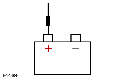
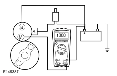
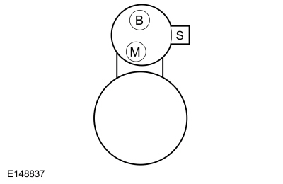
Connect a remote starter switch between starter solenoid “S” terminal and the battery positive terminal.
-
Connect the digital multimeter positive lead to the battery positive post. Connect the negative lead to the starter solenoid
"M" terminal.
-
Place gear select lever in Park or Neutral.
-
Engage the remote starter switch. Read and record the voltage. The voltage reading should be 0.5 volt or less.
-
If the voltage reading is 0.5 volt or less, perform Starter Motor - Ground Circuit Test in this section.
-
A voltage reading greater than 0.5 volt, this is an indication of excessive resistance in the connections, the positive battery
cable or in the starter solenoid. Remove the cables from the solenoid "B", "S" and "M" terminals. Clean the cables and connections
and reinstall the cables to the correct terminals. Repeat Steps 3 through 6.
-
If the voltage reading is still greater than 0.5 volt when checked at the "M" terminal, move the digital multimeter negative
lead to the starter solenoid “B” terminal and repeat Step 5.
-
If the voltage reading at the "B" terminal is lower than 0.5 volt, the concern is in the connections at the starter solenoid
or in the solenoid contacts. Install a new starter motor.
REFER to:
Starter Motor
(303-06A Starting System - 3.7L Duratec (227kW/301PS), Removal and Installation).
-
If the voltage reading taken at the solenoid "B" terminal is greater than 0.5 volt after cleaning the cables and connections
at the solenoid, the concern is in the positive battery cable connection or in the positive battery cable itself. Clean the
positive battery cable connection. If this does not resolve the concern, install a new positive battery cable.
REFER to:
Battery Cables - 3.7L Duratec (227kW/301PS)
(414-01 Battery, Mounting and Cables, Removal and Installation).
Starter Motor - Ground Circuit Test
WARNING:
Before beginning any service procedure in this section, refer to Safety Warnings in section 100-00 General Information. Failure
to follow this instruction may result in serious personal injury.
REFER to:
Health and Safety Precautions
(100-00 General Information, Description and Operation).
A slow cranking condition can be caused by resistance in the ground or return portion of the cranking circuit. This procedure
will check the voltage drop in the ground circuit.
-
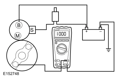
Connect a remote starter switch between starter solenoid "S" terminal and the battery positive terminal.
-
Connect the digital multimeter positive lead to the starter motor housing (the connection must be clean and free of rust or
grease). Connect the negative lead to the negative battery terminal.
-
Place gear select lever in Park or Neutral.
-
Engage the remote starter switch and crank the engine. Read and record the voltage reading. The reading should be 0.5 volt
or less.
-
If the voltage reading is greater than 0.5 volt, clean the negative cable connections at the battery, the body ground connections
and the starter ground connection. Retest.
-
If the voltage reading is greater than 0.5 volt, install a new negative battery cable.
REFER to:
Battery Cables - 3.7L Duratec (227kW/301PS)
(414-01 Battery, Mounting and Cables, Removal and Installation).
-
If the voltage reading is less than 0.5 volt and the engine still cranks slowly, install a new starter motor.
REFER to:
Starter Motor
(303-06A Starting System - 3.7L Duratec (227kW/301PS), Removal and Installation).
Copyright © Ford Motor Company
 Starter motor case