 WARNING:
When directed to drive the vehicle as part of this test, drive the vehicle on a hard surface in an area without traffic to
prevent a crash. Failure to follow these instructions may result in personal injury.
WARNING:
When directed to drive the vehicle as part of this test, drive the vehicle on a hard surface in an area without traffic to
prevent a crash. Failure to follow these instructions may result in personal injury.
| 308-07A Four-Wheel Drive Systems - Vehicles With: 6-Speed Automatic Transmission - 6F35 | 2013 - 2014 MKZ |
| Diagnosis and Testing | Procedure revision date: 07/18/2013 |
Principles of Operation
The AWD system may be referred to as a 4WD system in other service information and owner literature or messages located on the message center.
The AWD system is an active system, which means it not only responds to wheel slip between the front and rear axles but also has the ability to anticipate wheel slip and transfer torque to the rear wheels before the slip occurs. The AWD system is active all the time and requires no input from the operator.
The AWD system continuously monitors vehicle conditions and automatically adjusts the torque distribution between the front and rear wheels. During normal operation, most of the torque is delivered to the front wheels. If wheel slip between the front and rear wheels is detected, if the vehicle is under acceleration or if the vehicle is in an handling event, the AWD system increases and distributes torque to the rear wheels as needed. When the AWD system is functioning properly, there should be no perceived speed difference between the front and rear axles when launching or driving the vehicle on any non-uniform surface. Traction should be similar to a part time 4WD system in 4H (4X4 HIGH), but have no binding in turns.
If the spare tire is installed, the AWD system may disable automatically and enter FWD to protect driveline components. This condition may be indicated by AWD OFF message in the message center.
If there is a Check AWD message in the message center from using the spare tire, this indicator should turn off after reinstalling the repaired or replaced normal road tire and cycling the ignition OFF and ON. It is recommended to reinstall the repaired or replaced road tire as soon as possible. Major dissimilar tire sizes between the front and rear axles could cause the AWD system to stop functioning and default to FWD or damage the AWD system. If this condition occurs, a DTC will set and a Check AWD message is displayed on the message center.
AWD faults will be indicated by a driveline icon indicator in the IPC as well as the Check AWD message in the message center.
The AWD system consists of a power transfer unit, driveshaft, front and rear halfshafts, AWD relay module, PCM which includes the AWD control logic and an active torque coupling solenoid located in the Rear Drive Unit (RDU). Based on inputs to the PCM , the PCM sends a command to the AWD relay module. The amount of torque sent to the rear wheels is controlled by the AWD relay module sending a PWM duty cycle to the active torque coupling solenoid.
NOTE: The active torque coupling solenoid is not repairable. If a new component is required, the the active torque coupling solenoid and rear axle are installed as an assembly.
PCM inputs are:
PCM outputs are:
Heat Protection Rear Drive Unit (RDU)
During aggressive on road driving, the AWD system may implement a heat protection mode to protect the AWD clutch from damage. If the AWD system detects an overheat condition, it enters a locked mode. If the heat in the Rear Drive Unit (RDU) continues to rise once in the locked mode, the PCM disables the active torque coupling solenoid. This condition may be indicated by an AWD Temporarily Disabled message in the message center. To resume normal operation, stop the vehicle in a safe location and turn the engine for at least 10 minutes. After the engine is restarted and the AWD system has adequately cooled down, the AWD Temporarily Disabled message will turn off and normal AWD operation will return. In the event the engine is not stopped, the AWD Temporarily Disabled message will turn off when the system cools. Normal AWD operation returns once the message center displays AWD Restored.
Heat Protection Power Transfer Unit
During excessive use or trailer towing the AWD system may implement a heat protection mode to protect the power transfer unit from damage. The AWD system will reduce commanded torque only to situation deemed critical for minimal function. Once the maximum temperature limit is reached, then FWD only is commanded.
AWD Bar Code Identification
The AWD system on this vehicle is equipped with a bar coded active torque coupling solenoid to reduce the tolerance of electrical current to torque delivered to the active torque coupling solenoid. The active torque coupling solenoid bar code label can be found on the bottom of the Rear Drive Unit (RDU). The PCM uses this bar code information to match the clutch characteristics of the active torque coupling solenoid with the desired output torque. If the bar code information does not match the PCM information, driveline damage or driveability concerns can occur. Therefore, if the PCM needs to be replaced, the new PCM needs to be configured with the existing active torque coupling solenoid bar code information. If the rear drive axle need to be replaced, the existing PCM will need to be configured with the new active torque coupling solenoid bar code information. Carry out the AWD Drive Cycle.
Rear Drive Unit (RDU)
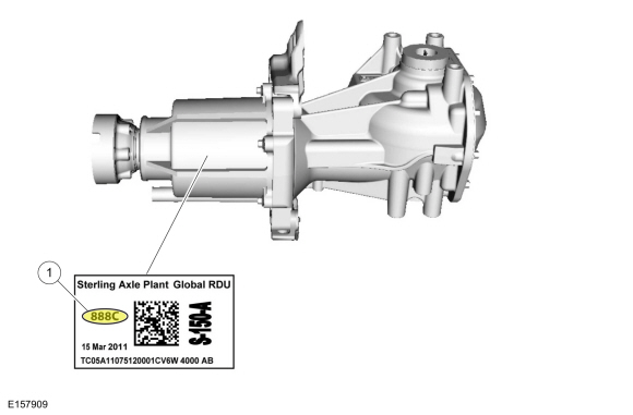
| Item | Description |
| 1 | Active torque coupling solenoid bar code |
Automatic Torque Coupling Configuration
NOTE: If the active torque coupling bar code information is not correct, Rear Drive Unit (RDU) damage or driveability concerns can occur.
AWD Drive Cycle
Carry out the AWD drive cycle after downloading the active torque coupling solenoid bar code information to the PCM .
NOTE: Always drive the vehicle in a safe manner according to driving conditions and obey all traffic laws.
Inspection and Verification
Visual Inspection Chart
| Mechanical | Electrical |
|---|---|
|
|
DTC Chart
| DTC | Description | Action |
| P164D | AWD ID Block Corrupted, Not Programmed | Enter the ID located on the Rear Drive Unit (RDU) and program into the PCM . |
| P181F | Clutch Control System Performance |
This is an internal
AWD
relay module fault. INSTALL a new
AWD
relay module.
REFER to: All-Wheel Drive (AWD) Module (308-07A Four-Wheel Drive Systems - Vehicles With: 6-Speed Automatic Transmission - 6F35, Removal and Installation). |
| P187B | Tire Size Out of Acceptable Range - AWD Disabled / Limited Function | GO to Pinpoint Test B B |
| P188B | AWD Clutch Control Circuit | GO to Pinpoint Test C C |
| P188C | AWD Relay Module Communication Circuit | CLEAR the Diagnostic Trouble Codes (DTCs). REPEAT the self-test. If DTC returns, GO to Pinpoint Test D D |
| P188D | AWD Relay Module Feedback Circuit | CLEAR the Diagnostic Trouble Codes (DTCs). REPEAT the self-test. If DTC returns, GO to Pinpoint Test D D |
Symptom Chart
Diagnostics in this manual assume a certain skill level and knowledge of Ford-specific diagnostic practices.
REFER to:
Diagnostic Methods
(100-00 General Information, Description and Operation).
In most circumstances, the PCM sets Diagnostic Trouble Codes (DTCs) to help guide with diagnostics. Refer to the DTC Chart before using the symptom chart. The Symptom column lists the vehicle condition. The Possible Sources column lists a detailed vehicle condition. The Action column lists the action to be performed to determine the cause of the condition. Each action lists the components that can cause the system and the individual components in that system. The components are listed in order of disassembly. Use the list of components and the required action to focus on disassembly inspections for the root cause of the concern.
| Symptom | Possible Sources | Action |
|---|---|---|
|
|
|
|
|
|
|
|
|
|
|
|
|
|
|
Pinpoint Tests
Diagnostic Overview
Diagnostics in this manual assume a certain skill level and knowledge of Ford-specific diagnostic practices.
REFER to:
Diagnostic Methods
(100-00 General Information, Description and Operation).
This pinpoint test is intended to diagnose the
AWD
system concern without on-demand or continuous Diagnostic Trouble Codes (DTCs).
Refer to Wiring Diagrams Cell 34 for schematic and connector information.
AWD System Functional Test
Normal Operation and Fault Conditions
The AWD system is an active system, which means it not only responds to wheel slip between the front and rear axles but also has the ability to anticipate wheel slip and transfer torque to the rear wheels before the slip occurs. The AWD system is active all the time and requires no input from the operator. The AWD system continuously monitors vehicle conditions and automatically adjusts the torque distribution between the front and rear wheels. During normal operation, most of the torque is delivered to the front wheels. If wheel slip between the front and rear wheels is detected, if the vehicle is under acceleration or if the vehicle is in a handling event, the AWD system increases and distributes torque to the rear wheels as needed. When the AWD system is functioning properly, there should be no perceived speed difference between the front and rear axles when launching or driving the vehicle on any uniform surface. Traction should be similar to a part time 4WD system in 4H (4X4 HIGH), but have no binding in turns.
WARNING:
When directed to drive the vehicle as part of this test, drive the vehicle on a hard surface in an area without traffic to
prevent a crash. Failure to follow these instructions may result in personal injury.
NOTE: Check related modules for Diagnostic Trouble Codes (DTCs). If Diagnostic Trouble Codes (DTCs) are set in other modules, diagnose those Diagnostic Trouble Codes (DTCs) first before continuing.
| A1 A1 CHECK FOR ACTIVE TORQUE COUPLING SOLENOID LOCK | ||||
Is driveline wind-up present in turns?
|
||||
| A2 A2 CHECK PCM (POWERTRAIN CONTROL MODULE) WHEEL SPEEDS | ||||
Are all 4 wheel speeds within 1.2 mph ( 2 km/h) of each other?
|
||||
| A3 A3 CHECK VEHICLE ACCELERATION IN A STRAIGHT LINE | ||||
Does the vehicle pulsate or shudder while accelerating?
|
||||
| A4 A4 CHECK VEHICLE TURNING ABILITY | ||||
Does the vehicle bind in the turn or resist turning?
|
||||
| A5 A5 CHECK TORQUE AT THE REAR WHEELS | ||||
Does the vehicle bind in the turn or resist turning?
|
Diagnostic Overview
Diagnostics in this manual assume a certain skill level and knowledge of Ford-specific diagnostic practices.
REFER to:
Diagnostic Methods
(100-00 General Information, Description and Operation).
This pinpoint test is intended to diagnose the wheels and tires, wheel speed sensors
ABS
module and
PCM
.
Refer to Wiring Diagrams Cell 34 for schematic and connector information.
Tire/Axle Out Of Acceptable Range
Normal Operation and Fault Conditions
The AWD system uses input data from the ABS module wheel speed sensor inputs to the PCM . A dissimilar spare tire size (other than the spare tire provided) or major dissimilar tire sizes or improperly inflated tires between the front and rear axles could cause the AWD system to stop functioning correctly.
DTC Fault Trigger Conditions
| DTC | Description | Fault Trigger Conditions |
|---|---|---|
| P187B | Tire Size Out of Acceptable Range - AWD Disabled / Limited Function | When the PCM detects an inappropriate size wheels/tires (greater than 5% difference in size across the front and rear axle or greater than 14% difference in size at one wheel on either the front or rear axle) installed. |
Possible Sources
WARNING:
When directed to drive the vehicle as part of this test, drive the vehicle on a hard surface in an area without traffic to
prevent a crash. Failure to follow these instructions may result in personal injury.
| B1 B1 CHECK FOR RECENT TIRE USAGE | ||||
Was a tire recently installed on the vehicle that was not originally supplied with the vehicle or has the mini spare been used?
|
||||
| B2 B2 CHECK TIRE SIZE AND BRAND | ||||
Are all 4 tires the same size and brand?
|
||||
| B3 B3 CHECK TIRE AIR PRESSURES | ||||
Are all 4 tires at the recommended air pressure?
|
||||
| B4 B4 CHECK PCM (POWERTRAIN CONTROL MODULE) WHEEL SPEEDS | ||||
Are all 4 wheel speeds within 1.2 mph ( 2 km/h) of each other?
|
||||
| B5 B5 CHECK FOR CORRECT PCM OPERATION | ||||
Is the concern still present?
|
Diagnostic Overview
Diagnostics in this manual assume a certain skill level and knowledge of Ford-specific diagnostic practices.
REFER to:
Diagnostic Methods
(100-00 General Information, Description and Operation).
This pinpoint test is intended to diagnosis the wiring, terminals, connectors,
AWD
relay module and
PCM
.
Refer to Wiring Diagrams Cell 34 for schematic and connector information.
AWD Clutch Control
Normal Operation and Fault Conditions
The AWD system uses data from other systems as inputs to the PCM . The PCM uses the inputs to determine the appropriate time to send a signal and have the AWD relay module energize the active torque coupling solenoid.
DTC Fault Trigger Conditions
| DTC | Description | Fault Trigger Conditions |
|---|---|---|
| P188B | AWD Clutch Control Circuit | When the PCM detects an open, a short to ground or voltage on the active torque coupling solenoid voltage supply and/or return circuit. |
Possible Sources
| C1 C1 CHECK THE ACTIVE TORQUE COUPLING SOLENOID CIRCUITS | |||||||||||||
Is the resistance between 1 to 3 ohms?
|
|||||||||||||
| C2 C2 CHECK THE ACTIVE TORQUE COUPLING SOLENOID CIRCUITS FOR AN OPEN | |||||||||||||
Is the resistance less than 3 ohms?
|
|||||||||||||
| C3 C3 CHECK THE ACTIVE TORQUE COUPLING SOLENOID CIRCUITS FOR A SHORT TO GROUND | |||||||||||||
Is the resistance greater than 10,000 ohms?
|
|||||||||||||
| C4 C4 CHECK THE ACTIVE TORQUE COUPLING SOLENOID CIRCUITS FOR A SHORT TOGETHER | |||||||||||||
Is the resistance greater than 10,000 ohms?
|
|||||||||||||
| C5 C5 CHECK THE ACTIVE TORQUE COUPLING SOLENOID CIRCUITS FOR A SHORT TO POWER | |||||||||||||
Is any voltage present?
|
|||||||||||||
| C6 C6 CHECK THE ACTIVE TORQUE COUPLING SOLENOID | |||||||||||||
Is the resistance between 1 and 3 ohms?
|
Diagnostic Overview
Diagnostics in this manual assume a certain skill level and knowledge of Ford-specific diagnostic practices.
REFER to:
Diagnostic Methods
(100-00 General Information, Description and Operation).
This pinpoint test is intended to diagnosis the wiring, terminals, connectors,
AWD
relay module and
PCM
.
Refer to Wiring Diagrams Cell 34 for schematic and connector information.
AWD Information Circuits
Normal Operation and Fault Conditions
The AWD system uses data from other systems as inputs to the PCM . The PCM uses the inputs to determine the appropriate time to send a signal and have the AWD relay module energize the active torque coupling solenoid.
DTC Fault Trigger Conditions
| DTC | Description | Fault Trigger Conditions |
|---|---|---|
| P188C | AWD Relay Module Communication Circuit | When the PCM detects an open, a short to ground or voltage on the command circuit. |
| P188D | AWD Relay Module Feedback Circuit | When the PCM detects an open, a short to ground or voltage on the feedback circuit. |
Possible Sources
| D1 D1 CHECK FOR AWD (ALL-WHEEL DRIVE) RELAY VOLTAGE | |||||||||||||
Is the voltage greater than 10 volts?
|
|||||||||||||
| D2 D2 CHECK FUSE 37 (15A) | |||||||||||||
Is the resistance less than 3 ohms?
|
|||||||||||||
| D3 D3 CHECK THE AWD (ALL-WHEEL DRIVE) RELAY MODULE POWER CIRCUIT FOR AN OPEN | |||||||||||||
Is the resistance less than 3 ohms?
|
|||||||||||||
| D4 D4 CHECK THE AWD (ALL-WHEEL DRIVE) RELAY MODULE GROUND CIRCUIT FOR AN OPEN | |||||||||||||
Is the voltage greater than 10 volts?
|
|||||||||||||
| D5 D5 CHECK THE AWD (ALL-WHEEL DRIVE) RELAY MODULE COMMAND AND FEEDBACK CIRCUITS FOR AN OPEN | |||||||||||||
Is the resistance less than 3 ohms?
|
|||||||||||||
| D6 D6 CHECK THE AWD (ALL-WHEEL DRIVE) RELAY MODULE COMMAND AND FEEDBACK CIRCUITS FOR A SHORT TO GROUND | |||||||||||||
Is the resistance greater than 10,000 ohms?
|
|||||||||||||
| D7 D7 CHECK THE AWD (ALL-WHEEL DRIVE) RELAY MODULE COMMAND AND FEEDBACK CIRCUITS FOR A SHORT TOGETHER | |||||||||||||
Is the resistance greater than 10,000 ohms?
|
|||||||||||||
| D8 D8 CHECK THE AWD (ALL-WHEEL DRIVE) RELAY MODULE COMMAND AND FEEDBACK CIRCUITS FOR A SHORT TO POWER | |||||||||||||
Is any voltage present?
|
Diagnostic Overview
Diagnostics in this manual assume a certain skill level and knowledge of Ford-specific diagnostic practices.
REFER to:
Diagnostic Methods
(100-00 General Information, Description and Operation).
This pinpoint test is intended to diagnose the wiring, terminals, connectors, wheels and tires, rear axle,
ABS
module,
PCM
and
AWD
relay module.
Refer to Wiring Diagrams Cell 34 for schematic and connector information.
Vehicle Binds in a Turn or Resists Turning/Pulsates or Shudders in a Straight Line
Normal Operation and Fault Conditions
The AWD system is an active system, which means it not only responds to wheel slip between the front and rear axles but also has the ability to anticipate wheel slip and transfer torque to the rear wheels before the slip occurs. The AWD system is active all the time and requires no input from the operator. The AWD system continuously monitors vehicle conditions and automatically adjusts the torque distribution between the front and rear wheels. During normal operation, most of the torque is delivered to the front wheels. If wheel slip between the front and rear wheels is detected, if the vehicle is under acceleration or if the vehicle is in a handling event, the AWD system increases and distributes torque to the rear wheels as needed. When the AWD system is functioning properly, there should be no perceived speed difference between the front and rear axles when launching or driving the vehicle on any uniform surface. Traction should be similar to a part time 4WD system in 4H (4X4 HIGH), but have no binding in turns.
Possible Sources
WARNING:
When directed to drive the vehicle as part of this test, drive the vehicle on a hard surface in an area without traffic to
prevent a crash. Failure to follow these instructions may result in personal injury.
| E1 E1 | ||||
Is a pulsation or shudder still present?
|
||||
| E2 E2 MONITOR THE CLUTCH STATUS PID | ||||
Is the duty cycle greater than 20%?
|
||||
| E3 E3 CHECK FOR THE CORRECT WHEEL SPEEDS | ||||
Are all 4 wheel speeds within 1.2 mph ( 2 km/h) of each other?
|
||||
| E4 E4 CHECK FOR CORRECT AWD RELAY MODULE OPERATION | ||||
Is the concern still present?
|
Copyright © Ford Motor Company

