
| 205-04 Front Drive Halfshafts | 2013 - 2014 MKZ |
| Removal and Installation | Procedure revision date: 07/9/2013 |
Removal
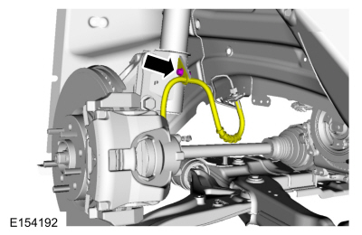
NOTICE: The front suspension height sensor must be disconnected from the lower control arm prior to servicing suspension components or damage to the suspension height sensor and/or the vehicle dynamic suspension system may occur. The sensor will need to be recalibrated after reassembly.
If equipped.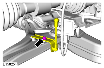
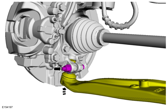
NOTICE: Do not use a prying device or separator fork between the ball joint and the wheel knuckle. Damage to the ball joint or ball joint seal may result. Only use the pry bar by inserting it into the lower arm body opening.
NOTICE: Use care when releasing the lower arm and wheel knuckle into the resting position or damage to the ball joint seal may occur.
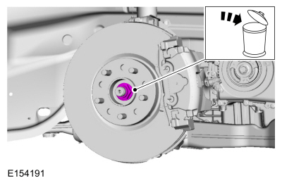
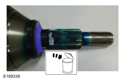
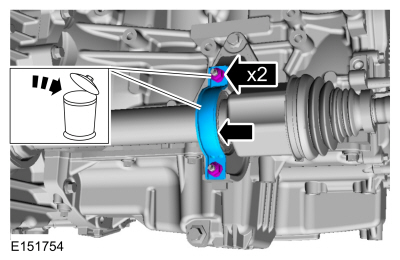
Discard the specified component. Follow local disposal regulations.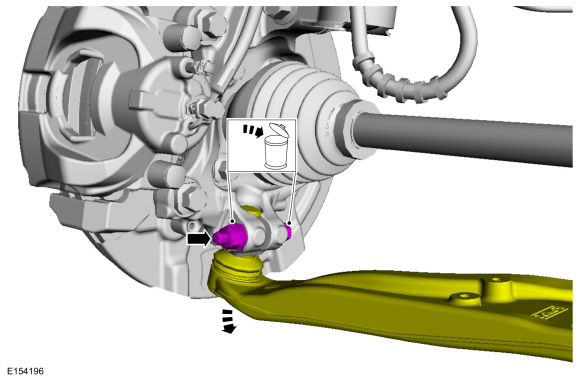
NOTICE: Do not bend the inner joint more than 18 degrees and the outer joint more than 45 degrees. Damage to the shaft will occur.
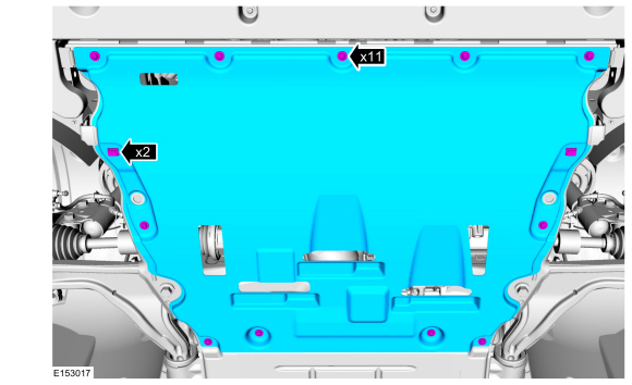
Relocate and support the component.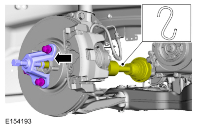
Installation
NOTE: Do not fully install the shaft at this time.
Using part: 4W1W-4N206-A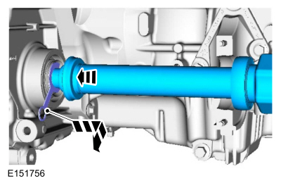
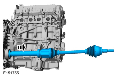
NOTE: Insert the intermediate shaft until the intermediate shaft bearing is centered in the concave groove of the intermediate shaft bearing bracket.
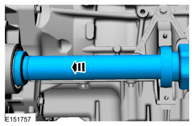
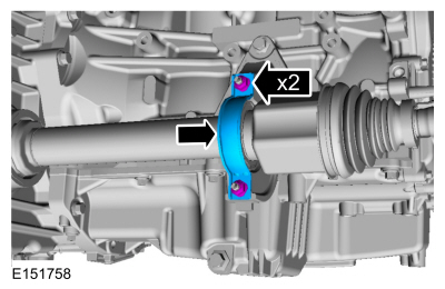
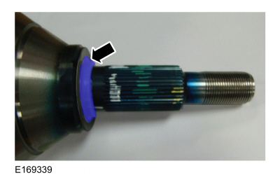
NOTE: Do not install the halfshaft any deeper than the centerline of the bearing with the centerline of the bracket. Over-installation of the halfshaft and pulling the halfshaft back out to align the bearing in the bracket could damage the intermediate shaft seal.
Special Tool(s) : 204-161 (T97P-1175-A) Installer, Halfshaft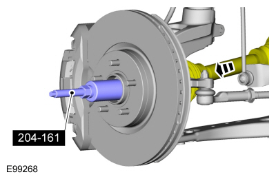
NOTICE: Do not tighten the front wheel hub nut with the vehicle on the ground. The nut must be tightened to specification before the vehicle is lowered onto the wheels. Wheel bearing damage will occur if the wheel bearing is loaded with the weight of the vehicle applied.
NOTICE: Install and tighten the new wheel hub nut to specification in a continuous rotation. Always install a new wheel hub nut after loosening or when not tightened to specification in a continuous rotation or damage to the components may occur.
NOTE: Apply the brake to keep the halfshaft from rotating.
Torque : 200 Nm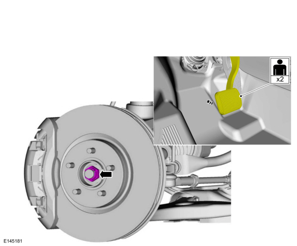
Copyright © Ford Motor Company