 WARNING:
Before beginning any service procedure in this section, refer to Safety Warnings in section 100-00 General Information. Failure
to follow this instruction may result in serious personal injury.
WARNING:
Before beginning any service procedure in this section, refer to Safety Warnings in section 100-00 General Information. Failure
to follow this instruction may result in serious personal injury.
| 303-03A Engine Cooling - 3.7L Duratec (227kW/301PS) | 2013 - 2014 MKZ |
| Removal and Installation | Procedure revision date: 10/30/2012 |
Removal
NOTICE: During engine repair procedures, cleanliness is extremely important. Any foreign material, including any material created while cleaning gasket surfaces, that enters the oil passages, coolant passages or the oil pan may cause engine failure.
WARNING:
Before beginning any service procedure in this section, refer to Safety Warnings in section 100-00 General Information. Failure
to follow this instruction may result in serious personal injury.
NOTE: Rotate the crankshaft in a clockwise direction only.
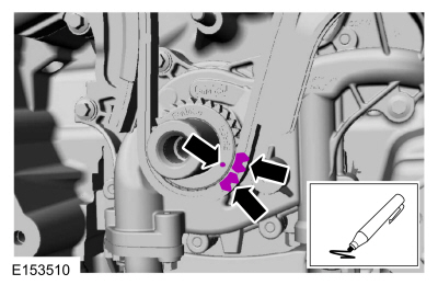
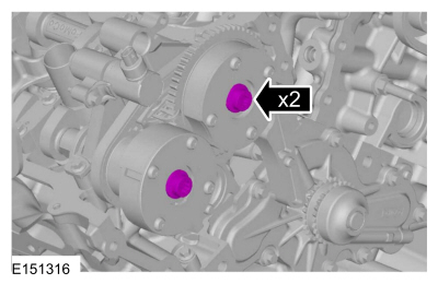
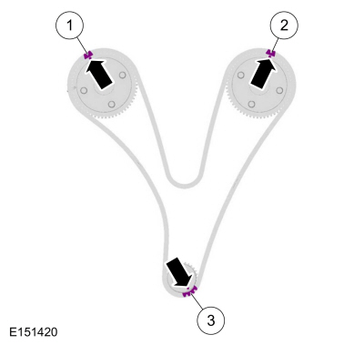
Align the timing marks.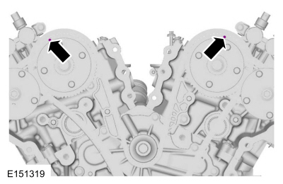

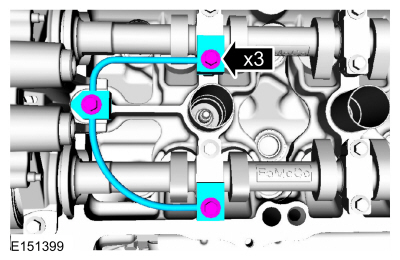
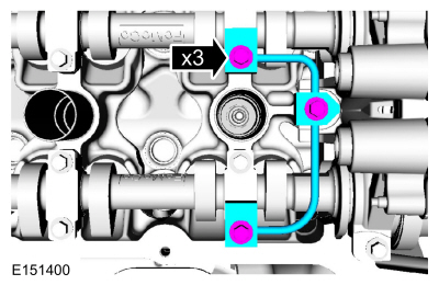
NOTE: The Camshaft Holding Tool will hold the camshafts in the TDC position.
Install Special Service Tool : 303-1248 Camshaft holding tools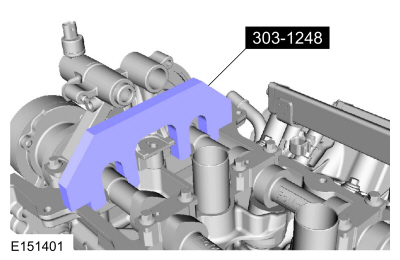
NOTE: The Camshaft Holding Tool will hold the camshafts in the TDC position.
Install Special Service Tool : 303-1248 Camshaft holding tools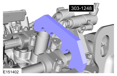
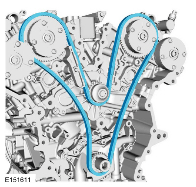
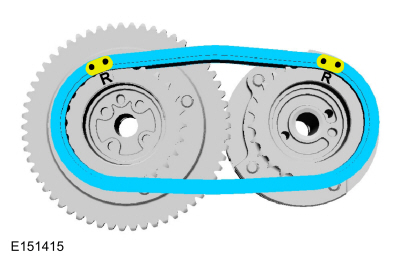
NOTE: The following 3 steps are for primary timing chains that the colored links are not visible.
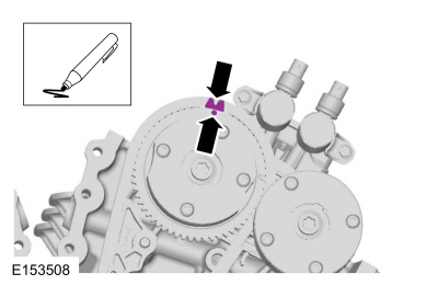
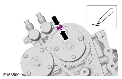
NOTE: The crankshaft sprocket timing mark should be between the 2 colored links.
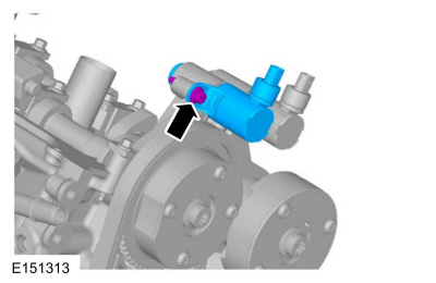
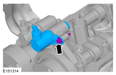
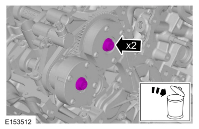
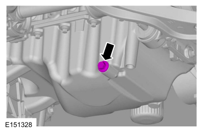
NOTE: A slight twisting motion will aid in the removal of the VVT oil control solenoid.
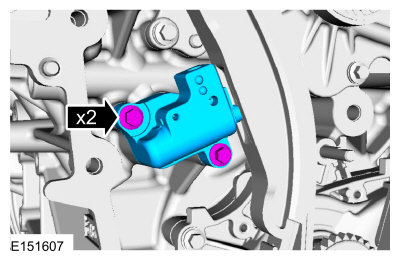
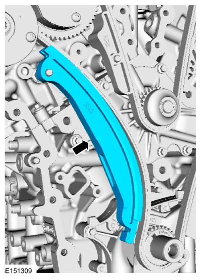
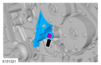
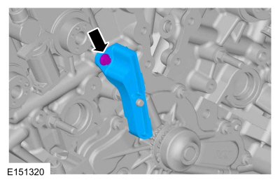
NOTICE: Do not use power tools to remove the bolt or damage to the LH primary timing chain guide may occur.
NOTE: The 2 VVT oil control solenoids are removed for clarity.
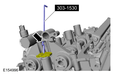
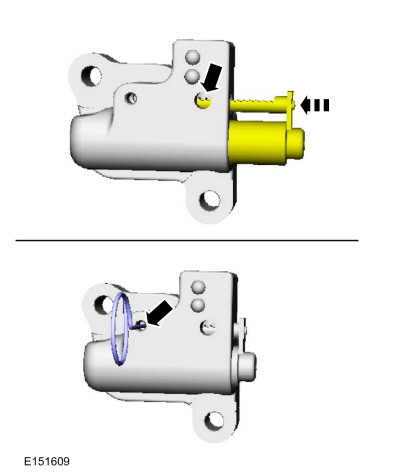
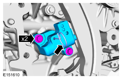
Install Special Service Tool : 303-1530 Tool, Chain Tensioner Hold Down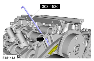
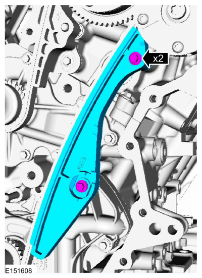
NOTICE: Do not use power tools to remove the bolt or damage to the RH primary timing chain guide may occur.
Installation
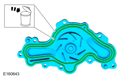
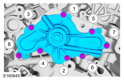
NOTE: Clean and inspect all sealing surfaces.

NOTICE: Any coolant that has accumulated in the oil pan must be drained from the pan and any residual coolant cleaned from the front of the engine and oil pan. Failure to remove all traces of the coolant can result in oil contamination and severe engine damage.
NOTE: Remove any residual coolant from the front of the engine and the oil pan using regulated, compressed air and clean, lint-free shop towels.
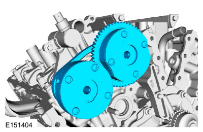
NOTE: It may be necessary to rotate the camshafts slightly, to install the RH secondary timing assembly.
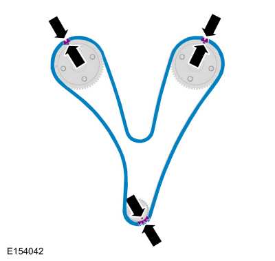
NOTE: Make sure the secondary timing chain is centered on the timing chain tensioner guides.
Remove Special Service Tool : 303-1530 Tool, Chain Tensioner Hold DownNOTE: It may be necessary to rotate the camshafts slightly, to align the timing marks.
NOTE: It may be necessary to rotate the camshafts slightly to remove slack from the timing chain to install the tensioner.
NOTICE: Do not use excessive force when installing the VVT oil control solenoid. Damage to the mega cap could cause the cylinder head to be inoperable. If difficult to install the VVT oil control solenoid, inspect the bore and VVT oil control solenoid to ensure there are no burrs, sharp edges or contaminants present on the mating surface. Only clean the external surfaces as necessary.
Torque :NOTICE: Do not use excessive force when installing the VVT oil control solenoid. Damage to the mega cap could cause the cylinder head to be inoperable. If difficult to install the VVT oil control solenoid, inspect the bore and VVT oil control solenoid to ensure there are no burrs, sharp edges or contaminants present on the mating surface. Only clean the external surfaces as necessary.
Torque :Copyright © Ford Motor Company