| 307-01A Automatic Transmission - Vehicles With: 6-Speed Automatic Transmission - 6F50 | 2013 - 2014 MKZ |
| Description and Operation | Procedure revision date: 09/21/2012 |
Direct (3, 5, R) Clutch Exploded View
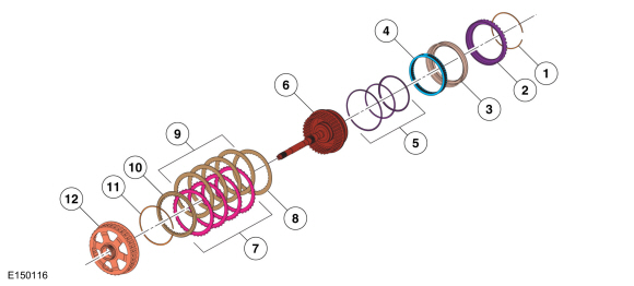
| Item | Description |
| 1 | Snap ring - direct clutch cylinder |
| 2 | Direct clutch cylinder |
| 3 | Direct clutch piston |
| 4 | Return spring - direct clutch piston |
| 5 | Direct clutch piston seals |
| 6 | Input shaft (part of direct/overdrive clutch assembly) |
| 7 | Direct clutch friction plates |
| 8 | Direct clutch wave spring |
| 9 | Direct clutch steel plates |
| 10 | Direct clutch pressure plate |
| 11 | Direct clutch snap ring |
| 12 | Rear planetary sun gear and shell assembly |
Direct (3, 5, R) Clutch Mechanical Operation
The direct clutch is a drive clutch that transfers power from the direct/overdrive hub and shaft assembly to the rear sun gear. The direct clutch is applied in 3rd and 5th gear and reverse.
Hydraulic pressure from the regulator valve in the valve body pushes the direct clutch piston against the direct clutch pack to apply the clutch. The input shaft transfers torque to the rear planetary sun gear as a result of the clutch being applied.
Direct (3, 5, R) Clutch Hydraulic Circuits (Applied in REVERSE)
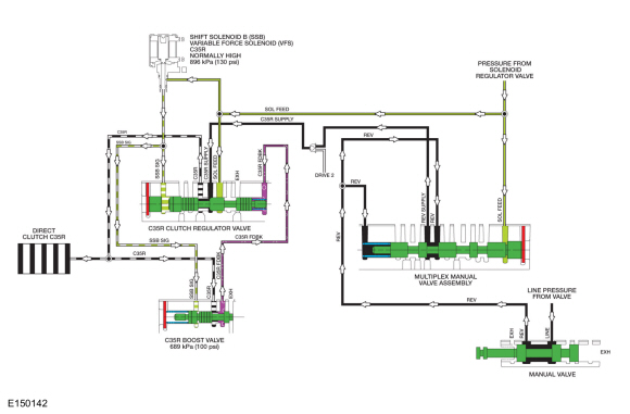
When the direct (3, 5, R) clutch is applied in REVERSE, LINE pressure from the pump is directed to the multiplex manual valve by the manual valve through the REV hydraulic circuit. The multiplex manual valve supplies the direct (3, 5, R) clutch regulator valve with pressure through the REV SUPPLY and C35R SUPPLY hydraulic circuits. To apply the direct (3, 5, R) clutch, Shift Solenoid B (SSB) applies varying solenoid pressure to the C35R clutch regulator and boost valves. As the C35R regulator valve moves, it supplies the direct (3, 5, R) clutch and C35R boost valve with regulated line pressure through the C35R circuit. The C35R boost valve directs the regulated line pressure to the opposite side of the C35R clutch regulator valve through the C35R FDBK circuit for controlled direct (3, 5, R) clutch engagement.
Direct (3, 5, R) Clutch Hydraulic Circuits (Applied in 3rd and 5th Gear)
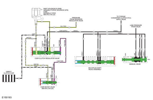
When the direct (3, 5, R) clutch is applied in 3rd and 5th gears, LINE pressure from the pump is directed to the multiplex shift valve by the manual valve through the DRIVE 1 hydraulic circuit. The multiplex shift valve directs the pressure to the direct (3, 5, R) clutch regulator valve through the DRIVE 2/C35R SUPPLY circuits. To apply the direct (3, 5, R) clutch, Shift Solenoid B (SSB) applies varying solenoid pressure to the C35R clutch regulator and boost valves. As the C35R regulator valve moves, it supplies the direct (3, 5, R) clutch and C35R boost valve with regulated line pressure through the C35R circuit. The C35R boost valve directs the regulated line pressure to the opposite side of the C35R clutch regulator valve through the C35R FDBK circuit for gradual direct (3, 5, R) clutch engagement.
For details on valve body hydraulic circuits and solenoid operation.
For additional information, refer to:
Transmission Description - System Operation and Component Description
(307-01A Automatic Transmission - Vehicles With: 6-Speed Automatic Transmission - 6F50, Description and Operation).
Copyright © Ford Motor Company