| 307-01A Automatic Transmission - Vehicles With: 6-Speed Automatic Transmission - 6F50 | 2013 - 2014 MKZ |
| Description and Operation | Procedure revision date: 09/20/2012 |
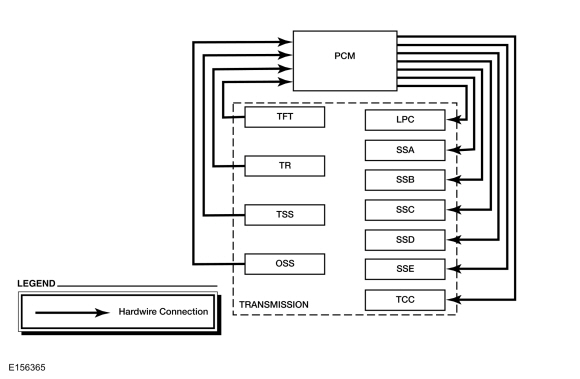
System Diagram
| Broadcast Message | Originating Module | Message Purpose |
|---|---|---|
| Engine Speed | PCM | Directly affects shift scheduling, TCC control, line pressure and transmission diagnostics. Indirectly affects shift pressure control. |
| Engine torque estimate | PCM | Directly affects shift pressure control, TCC control and transmission diagnostics. Indirectly affects shift scheduling and TCC scheduling. |
| APP | PCM | Directly affects shift scheduling, TCC scheduling and transmission diagnostics. Indirectly affects TCC control and shift control. |
| Commanded engine torque | PCM | Directly affects shift scheduling, TCC scheduling and transmission diagnostics. Indirectly affects shift control. |
| BPP | PCM | Directly affects shift scheduling and TCC scheduling |
System Operation
The PCM and its input/output network controls the following operations:
Shift timing
Line pressure (shift feel)
The transmission control strategy is separate from the engine control strategy in the PCM , although some of the input signals are shared. When determining the best operating strategy for transmission operation, the PCM uses input information from engine and driver related sensors and switches.
In addition, the PCM receives input signals from transmission related sensors and switches. The PCM uses these signals when determining transmission operating strategy.
Using all of these input signals, the PCM can determine when the time and conditions are right for a shift or when to apply or release the TCC . It also determines the best line pressure to optimize shift engagement feel. To accomplish this, the PCM uses output solenoids to control transmission operation.
Component Description
Sensors and Switches
The PCM controls the electronic functions of this transmission. The PCM receives input signals from engine and transmission sensors and uses these inputs to control line pressure, shift time, TCC and shift solenoids.
| Item | Description |
| TFT Sensor | This sensor is located in the transmission solenoid body. It is a temperature-sensitive device called a thermistor. The resistance value of the TFT sensor will vary with temperature change. The PCM monitors the voltage across the TFT sensor to determine the temperature of the transmission fluid. The PCM uses this initial signal to determine whether a cold start shift schedule is necessary. The cold start shift schedule allows delayed shifts when the transmission fluid is cold to help warm the transmission fluid. The PCM also inhibits TCC operation at low transmission fluid temperatures and adjusts line pressure for temperature. |
| TR Sensor | The TR sensor has a 6-pin electrical connector. The TR sensor is located on the inside of the transmission at the manual control lever. The TR sensor sends a signal to the PCM to start the vehicle in PARK and NEUTRAL. The TR sensor opens/ closes a set of 4 switches that are monitored by the PCM to determine the position of the manual control lever. |
| TSS Sensor | This TSS sensor is a Hall-effect pickup that sends a signal to the PCM that indicates transmission turbine shaft input speed. The TSS information is compared to engine rpm to determine TSS performance. TSS is also compared to OSS to determine shift quality and clutch performance. |
| OSS Sensor | The OSS sensor is a Hall-effect pickup, located on the transfer shaft drive gear, that sends a signal to the PCM to indicate transmission output speed. The OSS is used for shift scheduling. OSS is also compared to TSS to determine shift quality and clutch performance. |
System Diagram
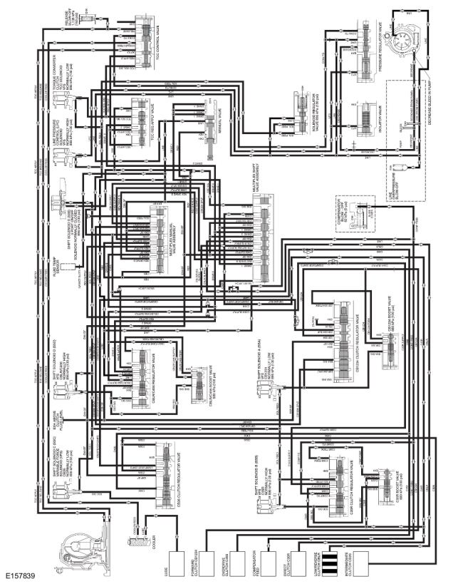
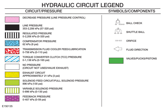
Hydraulic Circuit Identification Chart
| Circuit Name | Description |
| CB1234 | Regulated pressure from the forward (1, 2, 3, 4) clutch regulator valve to the forward clutch. |
| CB1234 FDBK | CB1234 pressure from the CB1234 boost valve supplied to the CB1234 clutch regulator valve to oppose movement of the valve from Shift Solenoid A (SSA) SIG pressure during forward (1, 2, 3, 4) clutch application. |
| CB1234 SUP | CB26FD/CB1234FD pressure supplied to the CB1234 regulator valve downstream of the CB26FD/CB1234FD check ball. |
| CB26 | Regulated pressure supplied to the intermediate (2, 6) clutch in 2nd and 6th gears. |
| CB26FD/CB1234FD | DRIVE 2 or DRIVE B pressure directed to the CB26 and CB1234 regulator valves by the DRIVE 2/DRIVE B shuttle ball. |
| C35R | Regulated C35R SUPPLY pressure from the direct (3, 5, R) regulator valve that supplies the direct (3, 5, R) clutch. |
| C35R FDBK | C35R pressure from the C35R boost valve supplied to the C35R clutch regulator valve to oppose movement of the valve from Shift Solenoid B (SSB) SIG pressure during direct (3, 5, R) clutch application. |
| C35R SUPPLY | DRIVE 2 or REV SUPPLY pressure directed to the 3, 5, R clutch regulator valve by the DRIVE 2/ REV SUPPLY shuttle ball. |
| C456/C456 SUPPLY | Regulated clutch pressure from the low/reverse/ overdrive (4, 5, 6) regulator valve directed to the overdrive (4, 5, 6) clutch in 4th, 5th, and 6th gears. |
| CBLR/C456 FDBK | CBLR/C456 SUPPLY pressure from the CBLR/ C456 boost valve supplied to the CBLR/C456 regulator valve to oppose movement of the valve from Shift Solenoid D (SSD) SIG pressure during low/ reverse and overdrive (4, 5, 6) clutch application. |
| CBLR/C456 SUPPLY | Regulated pressure from the low/reverse/overdrive (4, 5, 6) regulator valve to the multiplex shift valve assembly. The multiplex shift valve directs it to the overdrive clutch or the low/reverse clutch, depending on what position it is in. |
| CBLR/CBLR SUPPLY | Regulated pressure from the low/reverse/overdrive (4, 5, 6) regulator valve directed to the low/reverse clutch by the multiplex shift valve in LOW and REVERSE. |
| COMP FEED | Compensator feed pressure applied to the back side of clutches to keep the clutches from centrifugally applying. |
| CONV FD | Pressure from the pressure regulator valve to the torque converter clutch control valve, which supplies the valve to apply and release the torque converter clutch. |
| COOLER FEED | Pressure supplied to the transmission fluid cooler from the torque converter clutch control valve and feeds the LUBE circuit. |
| DECREASE | Pressure from the pressure regulator valve to the pump that raises and lowers the line pressure. |
| DRIVE 1 | Line pressure directed to the multiplex shift valve by the manual valve in DRIVE and LOW. |
| DRIVE 2 | DRIVE 1 pressure from the multiplex shift valve to the torque converter clutch regulator apply valve, DRIVE 2/DRIVE B shuttle ball, DRIVE 2/ REV SUPPLY shuttle ball and CBLR/C456 regulator valve. |
| DRIVE B | REV DRIVE B pressure directed to the DRIVE 2/ DRIVE B shuttle ball by the multiplex manual valve. |
| EXH | Fluid exhausted from the valves that drains to the sump area. |
| EXH BF | Fills the forward (1, 2, 3, 4), intermediate (2, 6) and low/reverse/overdrive (4, 5, 6) regulator valves and the multiplex shift and manual valves with fluid (no pressure). |
| LINE | Line pressure from the pump to the manual valve, solenoid regulator valve, fluid temperature sensor, low/reverse/overdrive (4, 5, 6) regulator valve, COMP FEED circuit and EXH BF circuit. |
| LPC | Full or regulated pressure from the Line Pressure Control (LPC) solenoid to the pressure regulator valve. |
| REG APPLY | Regulated DRIVE 2 pressure from the torque converter clutch regulator apply valve supplied to the torque converter clutch control valve to apply the torque converter clutch. |
| REV DRIVE B | DRIVE 1 pressure directed to the multiplex manual valve by the multiplex shift valve. |
| REV/REV SUPPLY | Pressure supplied to the multiplex shift valve assembly and the direct (3, 5, R) clutch regulator valve from the manual valve in REVERSE only. |
| SOL FEED | Regulated pressure from the solenoid regulator valve that supplies the shift, TCC and Line Pressure Control (LPC) solenoids, multiplex manual valve and the direct (3, 5, R) clutch regulator valve. |
| SSA SIG | Pressure supplied to the forward (1, 2, 3, 4) clutch regulator and boost valves from Shift Solenoid A (SSA) to direct regulated pressure to the forward clutch in 1st, 2nd, 3rd or 4th gears. |
| SSB SIG | Pressure supplied to the direct (3, 5, R) clutch regulator and boost valves from Shift Solenoid B (SSB) to direct regulated pressure to the direct clutch in 3rd and 5th gears and REVERSE. |
| SSC SIG | Pressure supplied to the intermediate (2, 6) clutch regulator and boost valves from Shift Solenoid C (SSC) to direct regulated pressure to the intermediate clutch in 2nd and 6th gears. |
| SSD SIG | Pressure supplied to the low/reverse/overdrive regulator and boost valves from Shift Solenoid D (SSD) to direct regulated pressure to the multiplex shift valve in LOW or REVERSE position or 4th, 5th and 6th gear. |
| SSE | Full solenoid pressure from Shift Solenoid E (SSE) to the torque converter clutch regulator valve and multiplex shift valve. |
| TCC APPLY | Pressure supplied to the torque converter from the TCC control valve to apply the torque converter clutch. |
| TCC RELEASE | Pressure supplied to the torque converter from the TCC control valve to release the torque converter clutch. |
| TCC SOL SIG | Full or regulated pressure from the TCC solenoid to the torque converter clutch regulator and control valves. |
| TFT | Line pressure directed to TFT sensor. |
Valve Body Maps for Solenoid and Line Pressure
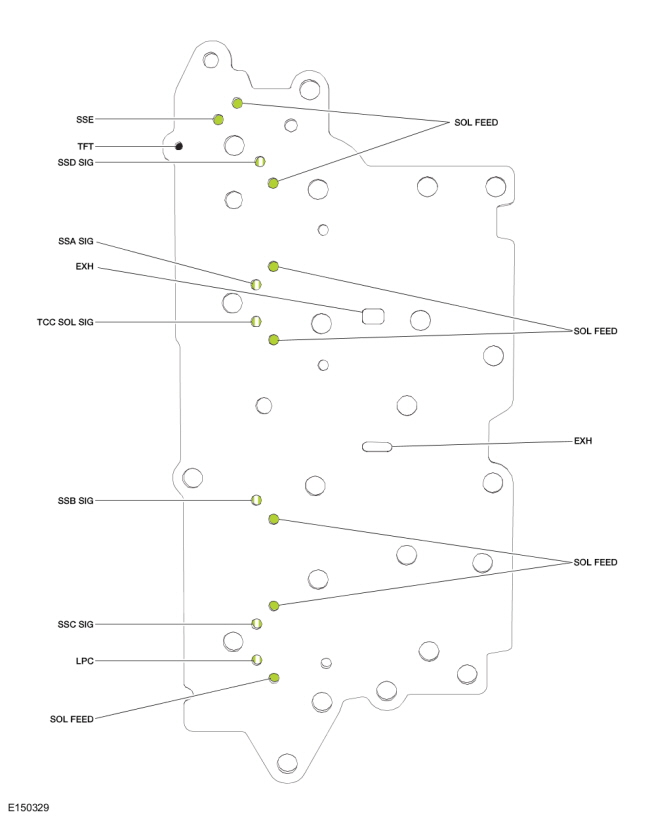
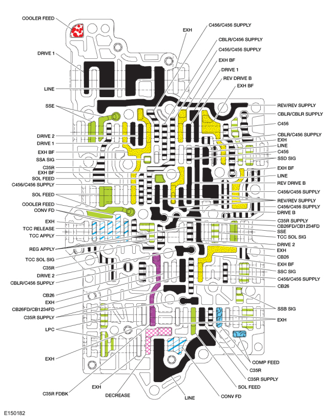
Solenoid Body Hydraulic Passages
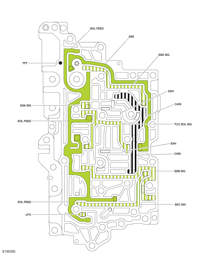
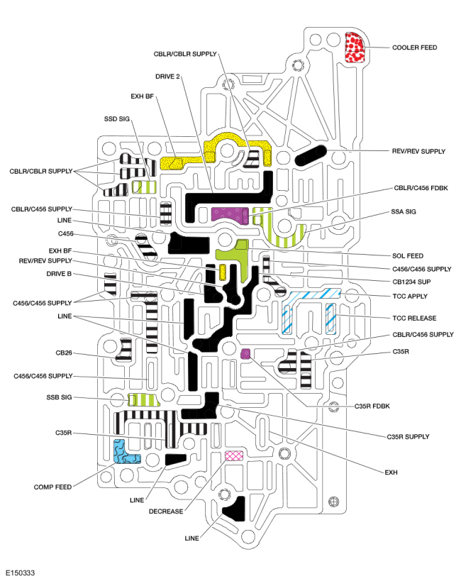
Cover Plate Hydraulic Passages
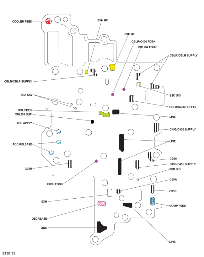
Transfer Plate Hydraulic Passages (Top View)
Transfer Plate Hydraulic Passages (Bottom View)
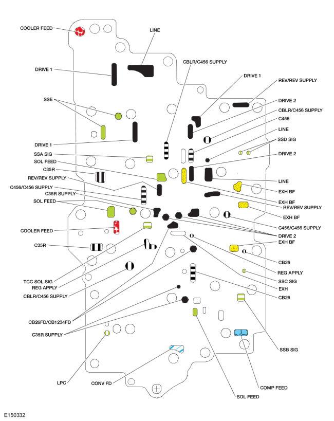
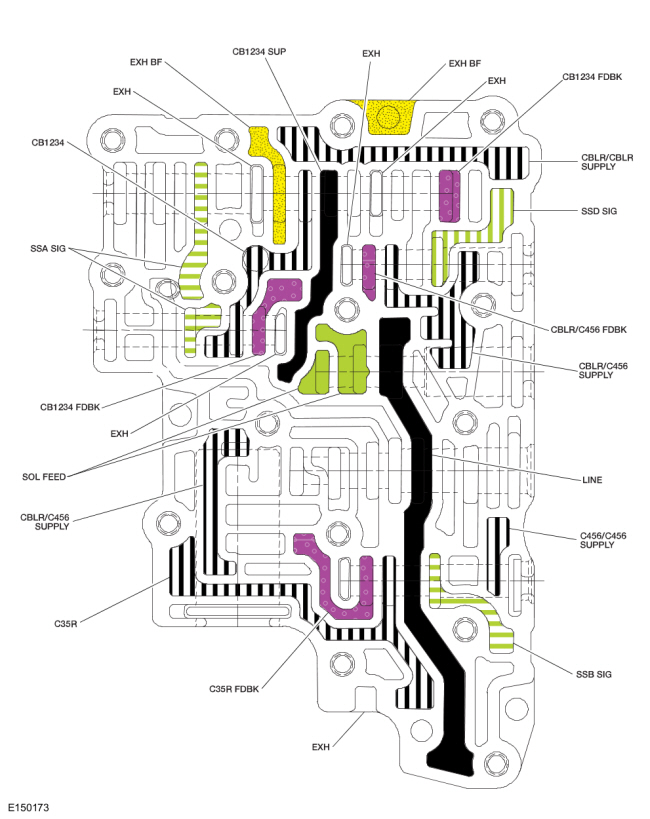
Center Spacer Plate Hydraulic Passages
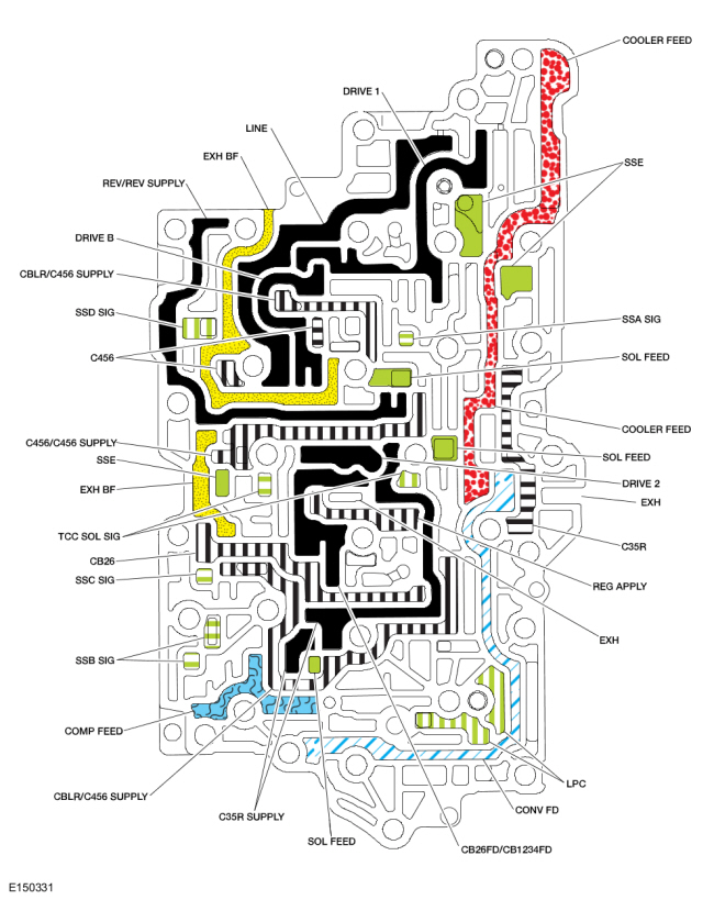
Valve Body Hydraulic Passages (Top View)
Valve Body Hydraulic Passages (Bottom View)
Lower Spacer Plate Hydraulic Passages
Lower Valve Body Hydraulic Passages
Line Pressure Hydraulic Circuits (Shown with the Manual Valve in the DRIVE Position)
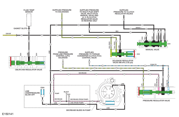
Line Pressure Hydraulic Circuits
The PCM controls line pressure with the Line Pressure Control (LPC) solenoid. This affects shift feel and apply component operation.
When the engine is running, the pump supplies pressure to the pressure regulator valve, which is controlled by the Line Pressure Control (LPC) solenoid. The pressure regulator valve controls the line pressure.
The line pressure circuit supplies the manual valve. The manual valve directs the line pressure to either the REV/REV SUPPLY circuit when the manual control lever is in the REVERSE position or the DRIVE 1 circuit when the manual control lever is in the DRIVE or LOW position.
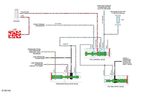
Lubrication Circuits (Torque Converter Clutch (TCC) Released)
Lubrication Circuits (Torque Converter Clutch [TCC] Applied)
Lubrication Hydraulic Circuits
Lubrication for the transmission is supplied by the transmission fluid cooler return tube. Transmission fluid is sent to the transmission fluid cooler from the TCC control valve.
LINE pressure supplied to the pressure regulator valve is sent to the TCC control valve as CONV FD pressure. During TCC release, the TCC control valve sends the transmission fluid to the torque converter to release the clutch. The transmission fluid returns to the TCC control valve from the torque converter and is directed to the transmission fluid cooler on the COOLER FEED circuit.
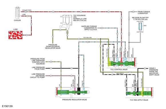
Torque Converter Hydraulic Circuits (Torque Converter Clutch [TCC] Applied)
Torque Converter Hydraulic Circuits
The PCM controls the TCC solenoid. The TCC solenoid applies hydraulic pressure to the TCC control and regulator apply valves through the TCC SOL SIG circuit. Regulated DRIVE 2 pressure from the multiplex shift valve is directed to the TCC control valve by the TCC regulator apply valve through the REG APPLY circuit. The TCC control valve directs pressure from the REG APPLY circuit to the TCC APPLY circuit to apply the clutch.
The transmission fluid returns to the TCC control valve through the TCC RELEASE hydraulic circuit. The TCC control valve opens the TCC RELEASE circuit to exhaust, so the TCC RELEASE circuit is not pressurized when the TCC is applied.
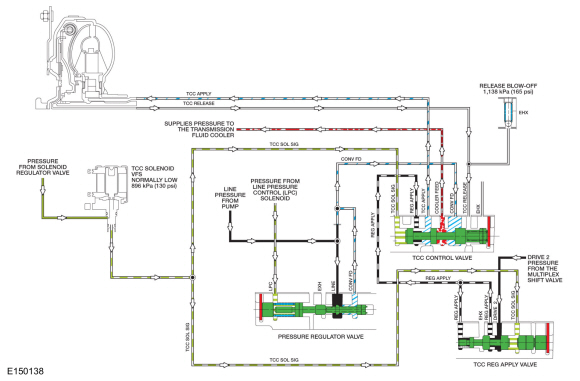
Torque Converter Hydraulic Circuits (Torque Converter Clutch [TCC] Released)
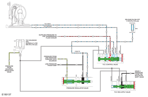
When the TCC is released, The TCC solenoid does not apply hydraulic pressure to the TCC control or regulator apply valves. The TCC control valve, in this position, directs hydraulic pressure from the CONV FD circuit to the torque converter through the TCC RELEASE hydraulic circuit and it returns to the TCC control valve through the TCC APPLY circuit.
Solenoid Hydraulic Circuits
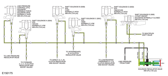
Solenoid Hydraulic Circuits
LINE pressure from the pump is directed to the individual shift, TCC and Line Pressure Control (LPC) solenoids by the solenoid regulator valve on the SOL FEED circuit. The solenoids, controlled by the PCM , direct the fluid to the valves that they control.
The Line Pressure Control (LPC) solenoid sends varying pressure to the line pressure regulator valve to control line pressure.
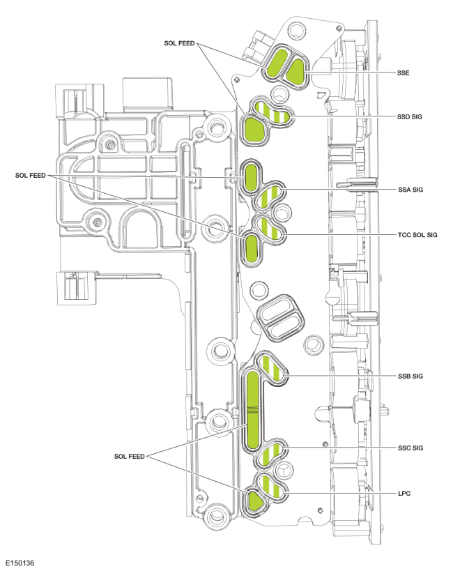
Solenoid Body
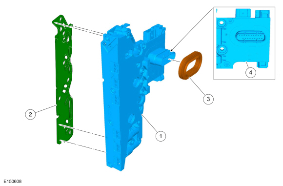
| Item | Description |
| 1 | Solenoid body |
| 2 | Solenoid body filter |
| 3 | Seal-solenoid body electrical connector |
| 4 | Internal wiring harness frame |
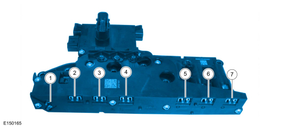
| Item | Description |
| 1 | Shift Solenoid E (SSE) |
| 2 | Shift Solenoid D (SSD) |
| 3 | Shift Solenoid A (SSA) |
| 4 | TCC solenoid |
| 5 | Shift Solenoid B (SSB) |
| 6 | Shift Solenoid C (SSC) |
| 7 | Line Pressure Control (LPC) solenoid |
Solenoid Body
The solenoid body contains 7 solenoids: 5 shift solenoids Shift Solenoid A (SSA), Shift Solenoid B (SSB), Shift Solenoid C (SSC), Shift Solenoid D (SSD) and Shift Solenoid E (SSE), 1 TCC solenoid and 1 Line Pressure Control (LPC) solenoid. The TFT sensor is located in the solenoid body. The solenoid body is serviced as an assembly.
The solenoid body has a unique strategy data file that must be downloaded to the PCM . There is a 7- digit solenoid body identification and a 13-digit solenoid body strategy for each solenoid body. When a new solenoid body or transmission is installed, the scan tool must be used to get the solenoid body strategy data file and download it into the PCM .
If the PCM is replaced and the PCM data cannot be inhaled or exhaled, the solenoid body identification and solenoid body strategy must be downloaded into the PCM .
This transmission uses 3 types of solenoids: On/Off, normally low and normally high. On/Off solenoids open or close hydraulic passages based on the voltage signal it receives. Normally low solenoids provide hydraulic pressure proportional to supplied current. A normally low solenoid will not provide pressure without current, while it will supply high pressure with high current. Normally high solenoids provide pressure inversely proportional to supplied current. Normally high solenoids provide full output of pressure with no current and very low pressure with high current.
ON/OFF Solenoids
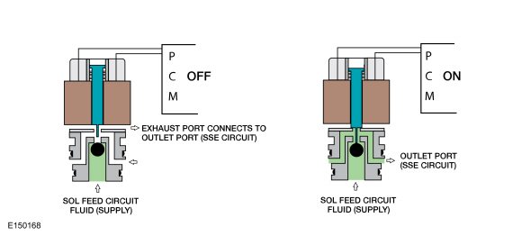
| Item | Description |
| Shift Solenoid E (SSE) | Normally closed solenoid that blocks SOL FEED pressure from the Shift Solenoid E (SSE) circuit. When energized, pressure from the Shift Solenoid E (SSE) circuit positions the multiplex shift valve to direct CBLR/C456 SUPPLY pressure to the low reverse clutch. |
Normally Low Solenoids
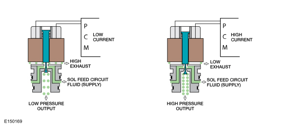
| Item | Description |
| Shift Solenoid A (SSA) | Shift Solenoid A (SSA) blocks SOL FEED pressure from the Shift Solenoid A (SSA) SIG circuit when low current is supplied. When energized, Shift Solenoid A (SSA) SIG pressure positions the CB1234 clutch regulator and boost valves to direct CB1234 SUP pressure to apply the forward clutch. |
| Shift Solenoid C (SSC) | Shift Solenoid C (SSC) blocks SOL FEED pressure to the Shift Solenoid C (SSC) SIG circuit when low current is supplied. When energized, Shift Solenoid C (SSC) SIG pressure positions the CB26 clutch regulator valve to direct CB26FD/CB1234FD pressure to apply the intermediate clutch. |
| TCC solenoid | The TCC solenoid is used in the transmission control system to control the application, modulation and release of the torque converter clutch. The TCC solenoid blocks SOL FEED pressure to the TCC SOL SIG circuit when low current is supplied. When energized, TCC SOL SIG pressure positions the TCC reg apply and control valves to direct REG APPLY pressure to apply the torque converter. |
Normally High Solenoids
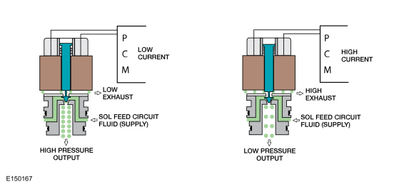
| Item | Description |
| Shift Solenoid B (SSB) | Shift Solenoid B (SSB) feeds SOL FEED pressure to the Shift Solenoid B (SSB) SIG circuit to position the direct (3,5,R) clutch regulator and boost valves to apply the direct (3,5,R) clutch. When energized, Shift Solenoid B (SSB) blocks Shift Solenoid B (SSB) SIG to position the direct clutch (3,5,R) regulator and boost valves to release the direct (3,5,R) clutch. |
| Shift Solenoid D (SSD) | Shift Solenoid D (SSD) feeds SOL FEED pressure to the Shift Solenoid D (SSD) SIG circuit to position the CBLR/C456 regulator and boost valves to apply either the low/ reverse clutch or the overdrive (4,5,6) clutch. When energized, Shift Solenoid D (SSD) blocks Shift Solenoid D (SSD) SIG to position the CBLR/C456 regulator and boost valves to release either the low/reverse clutch or the overdrive (4,5,6) clutch. |
| Line Pressure Control (LPC) solenoid | The Line Pressure Control (LPC) solenoid is used to apply resistive force to the main regulator valve to adjust line pressure. Line pressure is inversely proportional to the current supplied to the Line Pressure Control (LPC) solenoid. As current decreases, line pressure increases. |
Park
Park Clutch Application Chart
| Gear | Forward (1,2,3,4) | Direct (3,5,R) | Intermediate (2,6) | Low / Reverse (1,R) | Overdrive (4,5,6) | Low-OWC |
| Park | H | |||||
| Planetary Components | Front sun | Rear sun | Rear sun | Rear carrier/ center ring | Rear carrier/ center ring | Rear carrier/ center ring |
H = Holding
Park Position Solenoid Operation Chart
| Base Selector Lever Position | PCM Commanded Gear | SSA NL (1,2,3,4) | SSB NH (3,5,R) | SSC NL (2,6) | SSD NH (1,R,4,5,6) | SSE (On/ Off) NC | TCC NL |
| P | P | Off | On | Off | Off | On | Off |
NC = Normally Closed
NH = Normally High
NL = Normally Low
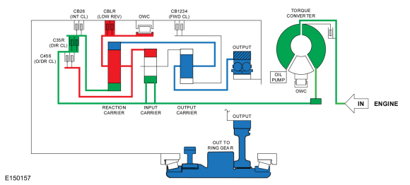
Powerflow
Reverse
Reverse Clutch Application Chart
| Gear | Forward (1,2,3,4) | Direct (3,5,R) | Intermediate (2,6) | Low / Reverse (1,R) | Overdrive (4,5,6) | Low-OWC |
| Reverse | D | H | ||||
| Planetary Components | Front sun | Rear sun | Rear sun | Rear carrier/ center ring | Rear carrier/ center ring | Rear carrier/ center ring |
H = Holding
D = Driving
Reverse Position Solenoid Operation Chart
| Base Selector Lever Position | PCM Commanded Gear | SSA NL (1,2,3,4) | SSB NH (3,5,R) | SSC NL (2,6) | SSD NH (1,R,4,5,6) | SSE (On/ Off) NC | TCC NL |
| R | R | Off | Off | Off | Off | On | Off |
NC = Normally Closed
NH = Normally High
NL = Normally Low
Powerflow
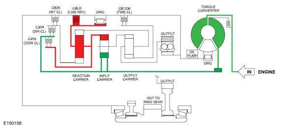
Neutral
Neutral Clutch Application Chart
| Gear | Forward (1,2,3,4) | Direct (3,5,R) | Intermediate (2,6) | Low / Reverse (1,R) | Overdrive (4,5,6) | Low-OWC |
| Neutral | H | |||||
| Planetary Components | Front sun | Rear sun | Rear sun | Rear carrier/ center ring | Rear carrier/ center ring | Rear carrier/ center ring |
H = Holding
Neutral Position Solenoid Operation Chart
| Base Selector Lever Position | PCM Commanded Gear | SSA NL (1,2,3,4) | SSB NH (3,5,R) | SSC NL (2,6) | SSD NH (1,R,4,5,6) | SSE (On/ Off) NC | TCC NL |
| N | N | Off | On | Off | Off | On | Off |
NC = Normally Closed
NH = Normally High
NL = Normally Low
Powerflow
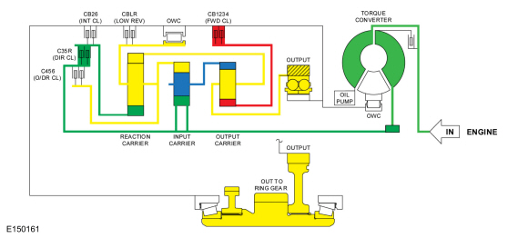
1st Gear
NOTE: The transmission operates differently in 1st gear above and below 8 kmh (5 mph). Transmission operation is the same below 8 kmh (5 mph) and in the LOW position.
1st Gear Above 8 kmh (5 mph) Clutch Application Chart
| Gear | Forward (1,2,3,4) | Direct (3,5,R) | Intermediate (2,6) | Low / Reverse (1,R) | Overdrive (4,5,6) | Low-OWC |
| 1st Gear D | H | H | ||||
| Planetary Components | Front sun | Rear sun | Rear sun | Rear carrier/ center ring | Rear carrier/ center ring | Rear carrier/ center ring |
H = Holding
1st Gear LOW Position and Below 8 kmh (5 mph) Clutch Application Chart
| Gear | Forward (1,2,3,4) | Direct (3,5,R) | Intermediate (2,6) | Low / Reverse (1,R) | Overdrive (4,5,6) | Low-OWC |
| 1st Gear D | H | H | H | |||
| Planetary Components | Front sun | Rear sun | Rear sun | Rear carrier/ center ring | Rear carrier/ center ring | Rear carrier/ center ring |
H = Holding
1st Gear Above 8 kmh (5 mph) Solenoid Operation Chart
| Base Selector Lever Position | PCM Commanded Gear | SSA NL (1,2,3,4) | SSB NH (3,5,R) | SSC NL (2,6) | SSD NH (1,R,4,5,6) | SSE (On/ Off) NC | TCC NL |
| D | 1 | On | On | Off | On | Off | Off |
NC = Normally Closed
NH = Normally High
NL = Normally Low
1st Gear LOW Position and Below 8 kmh (5 mph) Solenoid Operation Chart
| Base Selector Lever Position | PCM Commanded Gear | SSA NL (1,2,3,4) | SSB NH (3,5,R) | SSC NL (2,6) | SSD NH (1,R,4,5,6) | SSE (On/ Off) NC | TCC NL |
| L | 1 | On | On | Off | Off | On | Off |
NC = Normally Closed
NH = Normally High
NL = Normally Low
Powerflow
2nd Gear
2nd Gear Clutch Application Chart
| Gear | Forward (1,2,3,4) | Direct (3,5,R) | Intermediate (2,6) | Low / Reverse (1,R) | Overdrive (4,5,6) | Low-OWC |
| 2nd Gear D | H | H | ||||
| Planetary Components | Front sun | Rear sun | Rear sun | Rear carrier/ center ring | Rear carrier/ center ring | Rear carrier/ center ring |
H = Holding
2nd Gear Solenoid Operation Chart
| Base Selector Lever Position | PCM Commanded Gear | SSA NL (1,2,3,4) | SSB NH (3,5,R) | SSC NL (2,6) | SSD NH (1,R,4,5,6) | SSE (On/ Off) NC | TCC NL |
| D | 2 | On | On | On | On | Off | Off |
NC = Normally Closed
NH = Normally High
NL = Normally Low
Powerflow
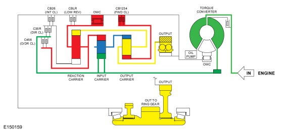
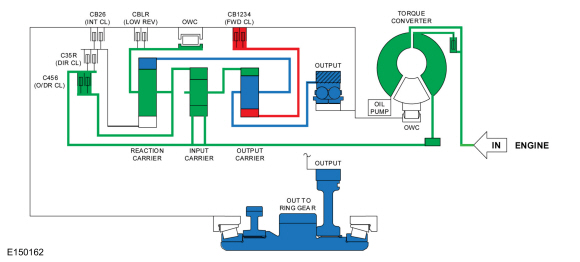
3rd Gear
3rd Gear Clutch Application Chart
| Gear | Forward (1,2,3,4) | Direct (3,5,R) | Intermediate (2,6) | Low / Reverse (1,R) | Overdrive (4,5,6) | Low-OWC |
| 3rd Gear D | H | D | ||||
| Planetary Components | Front sun | Rear sun | Rear sun | Rear carrier/ center ring | Rear carrier/ center ring | Rear carrier/ center ring |
H = Holding
D = Driving
3rd Gear Solenoid Operation Chart
| Base Selector Lever Position | PCM Commanded Gear | SSA NL (1,2,3,4) | SSB NH (3,5,R) | SSC NL (2,6) | SSD NH (1,R,4,5,6) | SSE (On/ Off) NC | TCC NL |
| D | 3 | On | Off | Off | On | Off | Off |
NC = Normally Closed
NH = Normally High
NL = Normally Low
Powerflow
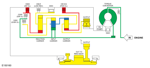
4th Gear
4th Gear Clutch Application Chart
| Gear | Forward (1,2,3,4) | Direct (3,5,R) | Intermediate (2,6) | Low / Reverse (1,R) | Overdrive (4,5,6) | Low-OWC |
| 4th Gear D | H | D | ||||
| Planetary Components | Front sun | Rear sun | Rear sun | Rear carrier/ center ring | Rear carrier/ center ring | Rear carrier/ center ring |
H = Holding
D = Driving
4th Gear Solenoid Operation Chart
| Base Selector Lever Position | PCM Commanded Gear | SSA NL (1,2,3,4) | SSB NH (3,5,R) | SSC NL (2,6) | SSD NH (1,R,4,5,6) | SSE (On/ Off) NC | TCC NL |
| D | 4 | On | On | Off | Off | Off | On/Off |
NC = Normally Closed
NH = Normally High
NL = Normally Low
Powerflow
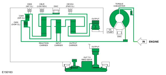
5th Gear
5th Gear Clutch Application Chart
| Gear | Forward (1,2,3,4) | Direct (3,5,R) | Intermediate (2,6) | Low / Reverse (1,R) | Overdrive (4,5,6) | Low-OWC |
| 5th Gear D | D | D | ||||
| Planetary Components | Front sun | Rear sun | Rear sun | Rear carrier/ center ring | Rear carrier/ center ring | Rear carrier/ center ring |
D = Driving
5th Gear Solenoid Operation Chart
| Base Selector Lever Position | PCM Commanded Gear | SSA NL (1,2,3,4) | SSB NH (3,5,R) | SSC NL (2,6) | SSD NH (1,R,4,5,6) | SSE (On/ Off) NC | TCC NL |
| D | 5 | Off | Off | Off | Off | Off | On/Off |
NC = Normally Closed
NH = Normally High
NL = Normally Low
Powerflow
Fail-safe Mode
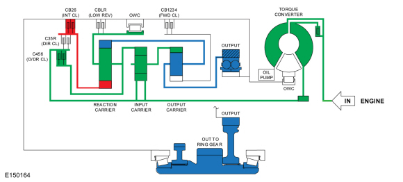
6th Gear
6th Gear Clutch Application Chart
| Gear | Forward (1,2,3,4) | Direct (3,5,R) | Intermediate (2,6) | Low / Reverse (1,R) | Overdrive (4,5,6) | Low-OWC |
| 6th Gear D | H | D | ||||
| Planetary Components | Front sun | Rear sun | Rear sun | Rear carrier/ center ring | Rear carrier/ center ring | Rear carrier/ center ring |
H = Holding
D = Driving
6th Gear Solenoid Operation Chart
| Base Selector Lever Position | PCM Commanded Gear | SSA NL (1,2,3,4) | SSB NH (3,5,R) | SSC NL (2,6) | SSD NH (1,R,4,5,6) | SSE (On/ Off) NC | TCC NL |
| D | 6 | Off | On | On | Off | Off | On/Off |
NC = Normally Closed
NH = Normally High
NL = Normally Low
Powerflow
Copyright © Ford Motor Company