| 204-05 Vehicle Dynamic Suspension | 2013 - 2014 MKZ |
| Description and Operation | Procedure revision date: 10/16/2012 |
System Operation
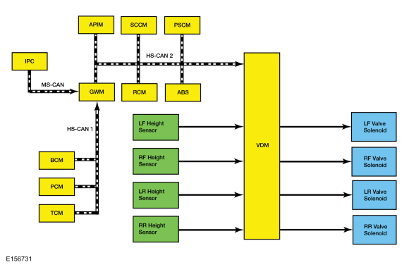
System Diagram
Network Message Chart
Module Network Input Messages - VDM
| Broadcast Message | Originating Module | Message Purpose |
|---|---|---|
| ABS active | ABS module | Indicates the current ABS activity, on or off. |
| Accelerator pedal position | PCM | This message is sent to the GWM and then to the VDM . Indicates the current accelerator pedal position. |
| Ambient air temperature | PCM | This message is sent to the GWM and then to the VDM . Indicates the current ambient air temperature. |
| Electrical power status | PCM | This message is sent to the GWM and then to the VDM . Indicates the current status of the vehicle battery and charging system. |
| Gear lever position | TCM | This message is sent to the GWM and then to the VDM . Indicates the current transmission gear status. Used to determine the amount of dampening required during vehicle operation. |
| Ignition status | BCM | This message is sent to the GWM and then to the VDM . Indicates the current ignition status; off, accessory, run, start, invalid or unknown. |
| Life cycle mode | BCM | This message is sent to the GWM and then to the VDM . Indicates the current vehicle life cycle; normal, factory, not used or transport. |
| Message center display | IPC or APIM | This message is sent to the GWM and then to the VDM . Indicates if the vehicle is equipped with a message center and indicates the current status of the message center. |
| Message center feature configuration | IPC or APIM | This message is sent to the GWM and then to the VDM . Indicates if the vehicle is equipped with a message center configuration. |
| Stability control brake active | ABS module | Indicates the current Electronic Stability Control (ESC) activity, on or off. |
| Steering wheel angle sensor | PSCM (vehicles not equipped with active park assist) | Indicates the current steering wheel angle relative to the straight ahead position. |
| Steering wheel angle sensor | SCCM (vehicles equipped with active park assist) | Indicates the current steering wheel angle relative to the straight ahead position. |
| Traction control mode | ABS module | Indicates the current traction control activity, on or off. |
| Vehicle configuration data | BCM | This message is sent to the GWM and then to the VDM . Indicates the current vehicle configuration and optional equipment. |
| Vehicle lateral acceleration | ABS module | Indicates the current lateral acceleration as measured by the sensors in the RCM and relayed by the ABS module. |
| Vehicle longitudinal acceleration | ABS module | Indicates the current longitudinal acceleration as measured by the sensors in the RCM and relayed by the ABS module. |
| Vehicle roll rate | ABS module | Indicates the current roll rate as measured by the sensors in the RCM . |
| Vehicle speed | PCM | This message is sent to the GWM and then to the VDM . Indicates the current vehicle speed in kilometers per hour. |
| Vehicle yaw rate | ABS module | Indicates the current yaw rate as measured by the sensors in the RCM . |
Vehicle Dynamic Suspension
The VDM is connected to the High Speed Controller Area Network (HS-CAN) to communicate with the ABS module, the PCM and other modules. With the information received the VDM monitors the heave, roll, pitch, cornering, braking and acceleration of the vehicle. Based on that information the VDM calculates the best action for each valve solenoid.
Component Description
Vehicle Dynamics Control Module (VDM)
The VDM monitors all sensor inputs and all High Speed Controller Area Network (HS-CAN) messages that relate to the vehicle dynamic suspension and then directly controls the valve solenoids. The VDM sends an individual electrical current to each valve solenoid to control the amount of damping required.
When one of the following components is installed new, disassembled, disconnected or removed the VDM requires calibration.
The calibration procedure is required for the system to learn the zero-position of the vehicle which means the vehicle must be on a level surface, must not be moving and cannot contain any passengers or cargo. The calibration procedure is carried out using a diagnostic scan tool. The calibration routine should not be performed with the vehicle raised off the ground or immediately after lowering the vehicle as the suspension will not be in a neutral position. The suspension must be neutralized before performing the calibration routine by driving the vehicle for a short distance such as around a parking lot.
Height Sensor
The height sensor uses a potentiometer to send a variable amount of voltage back to the VDM . The sensor has 3 circuits, one circuit is for the 5 volt sensor supply, one circuit is for sensor ground and one circuit is for the sensor output.
Valve Solenoid
The VDM uses a PWM output to control the valve solenoid. The solenoid will open or close the valve depending on the amount of current supplied by the VDM . The higher the current, the more the valve is opened, resulting in a "firm" suspension feel.
Copyright © Ford Motor Company