| 413-01 Instrumentation, Message Center and Warning Chimes
|
2013 - 2014 MKZ
|
| Diagnosis and Testing
|
Procedure revision date:
08/7/2013
|
Instrumentation, Message Center and Warning Chimes
DTC Chart: Instrument Panel Cluster (IPC)
Diagnostics in this manual assume a certain skill level and knowledge of Ford-specific diagnostic practices.
REFER to:
Diagnostic Methods
(100-00 General Information, Description and Operation).
Chart -
|
DTC
|
Description
|
Action
|
|
P0460:11
|
Fuel Level Sensor "A" Circuit: Circuit Short To Ground
|
For single sender L-shaped fuel tank,
GO to Pinpoint Test C
For dual sender saddle-type fuel tank,
GO to Pinpoint Test D
|
|
P0460:13
|
Fuel Level Sensor "A" Circuit: Circuit Open
|
For single sender L-shaped fuel tank,
GO to Pinpoint Test C
For dual sender saddle-type fuel tank,
GO to Pinpoint Test D
|
|
P1243:06
|
Second Fuel Pump Fault or Ground Fault: Algorithm Based Failure
|
GO to Pinpoint Test D
|
|
P1346:11
|
Fuel Level Sensor "B" Circuit: Circuit Short To Ground
|
GO to Pinpoint Test D
|
|
P1346:13
|
Fuel Level Sensor "B" Circuit: Circuit Open
|
GO to Pinpoint Test D
|
|
U0100:00
|
Lost Communication With ECM/PCM "A": No Sub Type Information
|
GO to Pinpoint Test AX
|
|
U0101:00
|
Lost Communication with TCM: No Sub Type Information
|
GO to Pinpoint Test AY
|
|
U0103:00
|
Lost Communication With Gear Shift Control Module A: No Sub Type Information
|
GO to Pinpoint Test AZ
|
|
U0104:00
|
Lost Communication With Cruise Control Module: No Sub Type Information
|
GO to Pinpoint Test BA
|
|
U0121:00
|
Lost Communication With Anti-Lock Brake System (ABS) Control Module: No Sub Type Information
|
GO to Pinpoint Test BB
|
|
U0122:00
|
Lost Communication With Vehicle Dynamics Control Module: No Sub Type Information
|
GO to Pinpoint Test BC
|
|
U0140:00
|
Lost Communication With Body Control Module: No Sub Type Information
|
GO to Pinpoint Test BD
|
|
U0151:00
|
Lost Communication With Restraints Control Module: No Sub Type Information
|
GO to Pinpoint Test BE
|
|
U0159:00
|
Lost Communication With Parking Assist Control Module "A": No Sub Type Information
|
GO to Pinpoint Test BF
|
|
U016A:00
|
Lost Communication With Global Positioning System Module: No Sub Type Information
|
GO to Pinpoint Test BG
|
|
U0193:00
|
Lost Communication With "Digital Audio Control Module A": No Sub Type Information
|
GO to Pinpoint Test BH
|
|
U0199:00
|
Lost Communication With "Door Control Module A": No Sub Type Information
|
GO to Pinpoint Test BI
|
|
U019E:00
|
Lost Communication With Transmission Range Control Module: No Sub Type Information
|
GO to Pinpoint Test BJ
|
|
U0212:00
|
Lost Communication With Steering Column Control Module: No Sub Type Information
|
GO to Pinpoint Test BK
|
|
U0232:00
|
Lost Communication With Side Obstacle Detection Control Module - Left: No Sub Type Information
|
GO to Pinpoint Test BL
|
|
U0233:00
|
Lost Communication With Side Obstacle Detection Control Module - Right: No Sub Type Information
|
GO to Pinpoint Test BL
|
|
U023A:00
|
Lost Communication With Image Processing Module A: No Sub Type Information
|
GO to Pinpoint Test BM
|
|
U0241:00
|
Lost Communication With Headlamp Control Module "A": No Sub Type Information
|
GO to Pinpoint Test BM
|
|
U0253:00
|
Lost Communication With Accessory Protocol Interface Module: No Sub Type Information
|
GO to Pinpoint Test BN
|
|
U0256:00
|
Lost Communication With Front Controls Interface Module "A": No Sub Type Information
|
GO to Pinpoint Test BO
|
|
U0260:00
|
Lost Communication With Seat Control Switch Module "A": No Sub Type Information
|
GO to Pinpoint Test BP
|
|
U0401:00
|
Invalid Data Received from ECM/PCM A: No Sub Type Information
|
This
sets when the
receives invalid network data for the speedometer, temperature or odometer data from the
. RETRIEVE and REPAIR all non-network Diagnostic Trouble Codes (DTCs) in the
and other modules on the network. Refer to Powertrain Control/Emissions Diagnosis (PC/ED) manual.
Refer to the appropriate section in Group 303 for the procedure.
|
|
U0401:81
|
Invalid Data Received from ECM/PCM A: Invalid Serial Data Received
|
This
sets when the
receives invalid network data for the speedometer, temperature or odometer data from the
. RETRIEVE and REPAIR all non-network Diagnostic Trouble Codes (DTCs) in the
and other modules on the network. Refer to Powertrain Control/Emissions Diagnosis (PC/ED) manual.
Refer to the appropriate section in Group 303 for the procedure.
|
|
U0401:82
|
Invalid Data Received from ECM/PCM A: Alive/Sequence Counter Incorrect/Not Updated
|
GO to Pinpoint Test AX
|
|
U0402:82
|
Invalid Data Received from TCM: Alive/Sequence Counter Incorrect/Not Updated
|
GO to Pinpoint Test AY
|
|
U0405:56
|
Invalid Data Received From Cruise Control Module: Invalid/Incompatible Configuration
|
This
sets when the
receives invalid network data for adaptive cruise control from the Cruise Control Module (C-CM). CHECK the vehicle service
history for recent service actions related to this module. This
sets due to incomplete or incorrect Programmable Module Installation (PMI) procedures. If there have been recent service
actions with this module, REPEAT the Programmable Module Installation (PMI) procedure as directed by the scan tool. If there
have been no recent service actions, INSTALL a new module to correct the failure to retain configuration data.
|
|
U0415:56
|
Invalid Data Received From Anti-Lock Brake System (ABS) Control Module: Invalid/Incompatible Configuration
|
This
sets when the
receives invalid network data for adaptive cruise control from the Cruise Control Module (C-CM). CHECK the vehicle service
history for recent service actions related to this module. This
sets due to incomplete or incorrect Programmable Module Installation (PMI) procedures. If there have been recent service
actions with this module, REPEAT the Programmable Module Installation (PMI) procedure as directed by the scan tool. If there
have been no recent service actions, INSTALL a new module to correct the failure to retain configuration data.
|
|
U0415:82
|
Invalid Data Received From Anti-Lock Brake System (ABS) Control Module: Alive/Sequence Counter Incorrect/Not Updated
|
GO to Pinpoint Test BB
|
|
U0416:82
|
Invalid Data Received From Vehicle Dynamics Control Module: Alive/Sequence Counter Incorrect/Not Updated
|
GO to Pinpoint Test BC
|
|
U0420:82
|
Invalid Data Received From Power Steering Control Module: Alive/Sequence Counter Incorrect/Not Updated
|
GO to Pinpoint Test BQ
|
|
U0422:00
|
Invalid Data Received From Body Control Module: No Sub Type Information
|
This
sets when the
receives invalid network
data from the
. RETRIEVE and REPAIR all non-network Diagnostic Trouble Codes (DTCs) in the
and other modules on the network.
REFER to:
Body Control Module (BCM)
(419-10 Multifunction Electronic Modules, Diagnosis and Testing).
|
|
U0424:80
|
Invalid Data Received From HVAC Control Module: ISO/SAE Reserved
|
This
sets when the
receives invalid network data for the outside air temperature display from the
module. RETRIEVE and REPAIR all non-network Diagnostic Trouble Codes (DTCs) in the
and other modules on the network. Refer to the appropriate section in Group 303 for the procedure.
|
|
U0424:81
|
Invalid Data Received From HVAC Control Module: Invalid Serial Data Received
|
This
sets when the
receives invalid network data for the outside air temperature display from the
module. RETRIEVE and REPAIR all non-network Diagnostic Trouble Codes (DTCs) in the
and other modules on the network. Refer to the appropriate section in Group 303 for the procedure.
|
|
U0429:82
|
Invalid Data Received From Steering Column Control Module: Alive/Sequence Counter Incorrect/Not Updated
|
GO to Pinpoint Test BK
|
|
U0431:82
|
Invalid Data Received From Body Control Module "A": Alive/Sequence Counter Incorrect/Not Updated
|
GO to Pinpoint Test BD
|
|
U0433:82
|
Invalid Data Received From Cruise Control Front Distance Range Sensor: Alive/Sequence Counter Incorrect/Not Updated
|
GO to Pinpoint Test BA
|
|
U0452:81
|
Invalid Data Received From Restraints Control Module: Invalid Serial Data Received
|
This
sets when the
receives invalid network data for the Belt-Minder® from the
. RETRIEVE and REPAIR all non-network Diagnostic Trouble Codes (DTCs) in the
and other modules on the network.
REFER to:
Airbag Supplemental Restraint System (SRS)
(501-20B Supplemental Restraint System, Diagnosis and Testing).
|
|
U0455:82
|
Invalid Data Received From Restraints Occupant Classification System Module: Alive/Sequence Counter Incorrect/Not Updated
|
GO to Pinpoint Test BR
|
|
U045A:56
|
Invalid Data Received From Parking Assist Control Module "A": Invalid/Incompatible Configuration
|
This
sets when the
receives invalid parking aid network data from the Parking Aid Module (PAM). CHECK the vehicle service history for recent
service actions related to this module. This
sets due to incomplete or incorrect Programmable Module Installation (PMI) procedures. If there have been recent service
actions with this module, REPEAT the Programmable Module Installation (PMI) procedure as directed by the scan tool. If there
have been no recent service actions, INSTALL a new module to correct the failure to retain configuration data.
|
|
U045A:81
|
Invalid Data Received From Parking Assist Control Module "A": Invalid Serial Data Received
|
This
sets when the
receives invalid network data for the parking aid setup from the Parking Aid Module (PAM). RETRIEVE and REPAIR all non-network
Diagnostic Trouble Codes (DTCs) in the Parking Aid Module (PAM) and other modules on the network. Refer to the appropriate section in Group 413 for the procedure.
|
|
U045A:82
|
Invalid Data Received From Parking Assist Control Module "A": Alive/Sequence Counter Incorrect/Not Updated
|
GO to Pinpoint Test BF
|
|
U0531:56
|
Invalid Data Received From Rear Gate Module: Invalid/Incompatible Configuration
|
This
sets when the
receives invalid parking aid network data from the
. CHECK the vehicle service history for recent service actions related to this module. This
sets due to incomplete or incorrect Programmable Module Installation (PMI) procedures. If there have been recent service
actions with this module, REPEAT the Programmable Module Installation (PMI) procedure as directed by the scan tool. If there
have been no recent service actions, INSTALL a new module to correct the failure to retain configuration data.
|
|
U0531:82
|
Invalid Data Received From Rear Gate Module: Alive/Sequence Counter Incorrect/Not Updated
|
GO to Pinpoint Test BS
|
|
U0533:56
|
Invalid Data Received From Side Obstacle Detection Control Module-Left Invalid / Incompatible Configuration
|
This
sets when the
receives invalid network data from the
. CHECK the vehicle service history for recent service actions related to this module. This
sets due to incomplete or incorrect Programmable Module Installation (PMI) procedures. If there have been recent service
actions with this module, REPEAT the Programmable Module Installation (PMI) procedure as directed by the scan tool. If there
have been no recent service actions, INSTALL a new module to correct the failure to retain configuration data.
|
|
U0533:82
|
Invalid Data Received From Side Obstacle Detection Control Module-Left: Alive/Sequence Counter Incorrect/Not Updated
|
GO to Pinpoint Test BL
|
|
U0534:56
|
Invalid Data Received From Side Obstacle Detection Control Module-Right: Invalid/Incompatible Configuration
|
This
sets when the
receives invalid network data from the
. CHECK the vehicle service history for recent service actions related to this module. This
sets due to incomplete or incorrect Programmable Module Installation (PMI) procedures. If there have been recent service
actions with this module, REPEAT the Programmable Module Installation (PMI) procedure as directed by the scan tool. If there
have been no recent service actions, INSTALL a new module to correct the failure to retain configuration data.
|
|
U0534:82
|
Invalid Data Received From Side Obstacle Detection Control Module-Right: Alive/Sequence Counter Incorrect/Not Updated
|
GO to Pinpoint Test BL
|
|
U053B:82
|
Invalid Data Received From Image Processing Module A: Alive/Sequence Counter Incorrect/Not Updated
|
GO to Pinpoint Test BM
|
|
U0542:82
|
Invalid Data Received From Headlamp Control Module "A": Alive/Sequence Counter Incorrect/Not Updated
|
GO to Pinpoint Test BM
|
|
U0557:82
|
Invalid Data Received From Front Controls Interface Module "A": Alive/Sequence Counter Incorrect/Not Updated
|
GO to Pinpoint Test BO
|
|
U0561:82
|
Invalid Data Received From Seat Control Switch Module "A": Alive/Sequence Counter Incorrect/Not Updated
|
GO to Pinpoint Test BP
|
|
U2100:00
|
Initial Configuration Not Complete: No Sub Type Information
|
CHECK the vehicle service history for recent service actions related to this module. This
sets due to incomplete or incorrect Programmable Module Installation (PMI) procedures. If there have been recent service
actions with this module, REPEAT the Programmable Module Installation (PMI) procedure as directed by the scan tool.
REFER to:
Module Configuration - System Operation and Component Description
(418-01 Module Configuration, Description and Operation).
If there have been no recent service actions, INSTALL a new module to correct the failure to retain configuration data.
|
|
U3000:04
|
Control Module: System Internal Failure
|
CLEAR the Diagnostic Trouble Codes (DTCs). REPEAT the self-test. If
U3000:04 is retrieved again, INSTALL a new
.
REFER to:
Instrument Panel Cluster (IPC)
(413-01 Instrumentation, Message Center and Warning Chimes, Removal and Installation).
|
|
U3000:46
|
Control Module: Calibration/Parameter Memory Failure
|
CLEAR the Diagnostic Trouble Codes (DTCs). REPEAT the self-test. If
U3000:46 is retrieved again, INSTALL a new
.
REFER to:
Instrument Panel Cluster (IPC)
(413-01 Instrumentation, Message Center and Warning Chimes, Removal and Installation).
|
|
U3003:16
|
Battery Voltage: Circuit Voltage Below Threshold
|
GO to Pinpoint Test BT
|
|
U3003:17
|
Battery Voltage: Circuit Voltage Above Threshold
|
GO to Pinpoint Test BU
|
|
U300A:64
|
Ignition Switch: Signal Plausibility Failure
|
U300A:64 sets in continuous memory when the
detects a messaged START input for 15 seconds or longer. Once the fault condition is detected, the
operates with limited functionality for 15 seconds then returns to full functionality. Diagnose the ignition start circuit
to the
.
REFER to:
Steering Wheel and Column Electrical Components
(211-05 Steering Wheel and Column Electrical Components, Diagnosis and Testing).
|
DTC Chart: Body Control Module (BCM)
Diagnostics in this manual assume a certain skill level and knowledge of Ford-specific diagnostic practices.
REFER to:
Diagnostic Methods
(100-00 General Information, Description and Operation).
Chart -
DTC Chart: Powertrain Control Module (PCM)
Diagnostics in this manual assume a certain skill level and knowledge of Ford-specific diagnostic practices.
REFER to:
Diagnostic Methods
(100-00 General Information, Description and Operation).
Chart -
|
DTC
|
Description
|
Action
|
|
P0460
|
Fuel Level Sensor "A" Circuit
|
Refer to Powertrain Control/Emissions Diagnosis (PC/ED) manual. If sent here from the Refer to Powertrain Control/Emissions Diagnosis (PC/ED) manual. manual, For single sender L-shaped fuel tank,
GO to Pinpoint Test C
For dual sender saddle-type fuel tank,
GO to Pinpoint Test D
|
|
P0461
|
Fuel Level Sensor "A" Circuit Range/Performance
|
Refer to Powertrain Control/Emissions Diagnosis (PC/ED) manual. If sent here from the Refer to Powertrain Control/Emissions Diagnosis (PC/ED) manual. manual, For single sender L-shaped fuel tank,
GO to Pinpoint Test C
For dual sender saddle-type fuel tank,
GO to Pinpoint Test D
|
|
P0462
|
Fuel Level Sensor "A" Circuit Low
|
Refer to Powertrain Control/Emissions Diagnosis (PC/ED) manual. If sent here from the Refer to Powertrain Control/Emissions Diagnosis (PC/ED) manual. manual, For single sender L-shaped fuel tank,
GO to Pinpoint Test C
For dual sender saddle-type fuel tank,
GO to Pinpoint Test D
|
|
P0463
|
Fuel Level Sensor "A" Circuit High
|
Refer to Powertrain Control/Emissions Diagnosis (PC/ED) manual. If sent here from the Refer to Powertrain Control/Emissions Diagnosis (PC/ED) manual. manual, For single sender L-shaped fuel tank,
GO to Pinpoint Test C
For dual sender saddle-type fuel tank,
GO to Pinpoint Test D
|
|
P2065
|
Fuel Level Sensor "B" Circuit
|
Refer to Powertrain Control/Emissions Diagnosis (PC/ED) manual. If sent here from the Refer to Powertrain Control/Emissions Diagnosis (PC/ED) manual. manual,
GO to Pinpoint Test D
|
|
P2066
|
Fuel Level Sensor "B" Circuit Range/Performance
|
Refer to Powertrain Control/Emissions Diagnosis (PC/ED) manual. If sent here from the Refer to Powertrain Control/Emissions Diagnosis (PC/ED) manual. manual,
GO to Pinpoint Test D
|
|
P2067
|
Fuel Level Sensor "B" Circuit Low
|
Refer to Powertrain Control/Emissions Diagnosis (PC/ED) manual. If sent here from the Refer to Powertrain Control/Emissions Diagnosis (PC/ED) manual. manual,
GO to Pinpoint Test D
|
|
P2068
|
Fuel Level Sensor "B" Circuit High
|
Refer to Powertrain Control/Emissions Diagnosis (PC/ED) manual. If sent here from the Refer to Powertrain Control/Emissions Diagnosis (PC/ED) manual. manual,
GO to Pinpoint Test D
|
|
P25B0
|
Fuel Level Sensor "A" Stuck
|
Refer to Powertrain Control/Emissions Diagnosis (PC/ED) manual. If sent here from the Refer to Powertrain Control/Emissions Diagnosis (PC/ED) manual. manual, For single sender L-shaped fuel tank,
GO to Pinpoint Test C
For dual sender saddle-type fuel tank,
GO to Pinpoint Test D
|
|
P25B1
|
Fuel Level Sensor "B" Stuck
|
Refer to Powertrain Control/Emissions Diagnosis (PC/ED) manual. If sent here from the Refer to Powertrain Control/Emissions Diagnosis (PC/ED) manual. manual,
GO to Pinpoint Test D
|
|
P25B2
|
Fuel Level Sensor "A" or "B" Stuck
|
Refer to Powertrain Control/Emissions Diagnosis (PC/ED) manual. If sent here from the Refer to Powertrain Control/Emissions Diagnosis (PC/ED) manual. manual, For single sender L-shaped fuel tank,
GO to Pinpoint Test C
For dual sender saddle-type fuel tank,
GO to Pinpoint Test D
|
|
All other DTCs
|
-
|
Refer to Powertrain Control/Emissions Diagnosis (PC/ED) manual.
Refer to the appropriate section in Group 303 for the procedure.
|
DTC Chart:
Diagnostics in this manual assume a certain skill level and knowledge of Ford-specific diagnostic practices.
REFER to:
Diagnostic Methods
(100-00 General Information, Description and Operation).
Chart -
DTC Chart: Steering Column Control Module (SCCM)
Diagnostics in this manual assume a certain skill level and knowledge of Ford-specific diagnostic practices.
REFER to:
Diagnostic Methods
(100-00 General Information, Description and Operation).
Chart -
Symptom Chart(s)
Symptom Chart: Instrument Panel Cluster (IPC)
Diagnostics in this manual assume a certain skill level and knowledge of Ford-specific diagnostic practices.
REFER to:
Diagnostic Methods
(100-00 General Information, Description and Operation).
Symptom Chart
|
Condition
|
Possible Sources
|
Actions
|
|
A module does not respond to the scan tool
|
-
Fuse
-
Wiring, terminals or connectors
-
Communication concern
-
Module
|
REFER to:
Communications Network
(418-00 Module Communications Network, Diagnosis and Testing).
|
|
The
is inoperative
|
Refer to the Pinpoint Test
|
GO to Pinpoint Test A
|
|
Multiple gauges, indicators, message center indicators, warnings and chimes are inoperative or always on
|
Refer to the Pinpoint Test
|
GO to Pinpoint Test A
|
|
A virtual gauge (speedometer, tachometer or temperature), is inoperative
|
Refer to the Pinpoint Test
|
GO to Pinpoint Test B
|
|
Incorrect fuel gauge indication - single sender L-shaped fuel tank
|
Refer to the Pinpoint Test
|
GO to Pinpoint Test C
|
|
Incorrect fuel gauge indication - dual sender saddle-type fuel tank
|
Refer to the Pinpoint Test
|
GO to Pinpoint Test D
|
|
The odometer is inoperative
|
Refer to the Pinpoint Test
|
GO to Pinpoint Test E
|
|
The
warning indicator is never or always on
|
Refer to the Pinpoint Test
|
GO to Pinpoint Test F
|
|
The airbag warning indicator is never or always on
|
Refer to the Pinpoint Test
|
GO to Pinpoint Test G
|
|
The brake warning indicator is never on
|
Refer to the Pinpoint Test
|
GO to Pinpoint Test H
|
|
The brake warning indicator is always on
|
Refer to the Pinpoint Test
|
GO to Pinpoint Test I
|
|
The electric park brake fault indicator is never or always on
|
Refer to the Pinpoint Test
|
GO to Pinpoint Test J
|
|
The
low beam malfunction indicator is never or always on
|
Refer to the Pinpoint Test
|
GO to Pinpoint Test K
|
|
The
-
turn signal or high beam indicator is never or always on
|
Refer to the Pinpoint Test
|
GO to Pinpoint Test L
|
|
The lights on indicator is never or always on
|
Refer to the Pinpoint Test
|
GO to Pinpoint Test M
|
|
The
is never or always on
|
Refer to the Pinpoint Test
|
GO to Pinpoint Test N
|
|
The PRNDL indicator is never on or never displays P
|
Refer to the Pinpoint Test
|
GO to Pinpoint Test O
|
|
The safety belt warning indicator is never or always on
|
Refer to the Pinpoint Test
|
GO to Pinpoint Test P
|
|
The stability-traction control indicator (sliding car icon) is never or always on
|
Refer to the Pinpoint Test
|
GO to Pinpoint Test Q
|
|
The stability-traction control disabled indicator (sliding car OFF icon) is never or always on
|
Refer to the Pinpoint Test
|
GO to Pinpoint Test R
|
|
The
warning indicator is never or always on
|
Refer to the Pinpoint Test
|
GO to Pinpoint Test S
|
Symptom Chart: Information And Message Center
Diagnostics in this manual assume a certain skill level and knowledge of Ford-specific diagnostic practices.
REFER to:
Diagnostic Methods
(100-00 General Information, Description and Operation).
Symptom Chart
|
Condition
|
Possible Sources
|
Actions
|
|
The message center is not operating correctly
|
Refer to the Pinpoint Test
|
GO to Pinpoint Test T
|
|
A virtual display is inoperative
|
Refer to the Pinpoint Test
|
GO to Pinpoint Test B
|
|
The compass is inoperative
|
Refer to the Pinpoint Test
|
GO to Pinpoint Test U
|
|
The outside air temperature display is inoperative or incorrect
|
Refer to the Pinpoint Test
|
GO to Pinpoint Test V
|
|
The Blind Spot Information System (BLIS®) off message center indicator is never or always on
|
Refer to the Pinpoint Test
|
GO to Pinpoint Test W
|
|
The charging system message center warning indicator is never or always on
|
Refer to the Pinpoint Test
|
GO to Pinpoint Test X
|
|
The cruise control message center indicator is never on
|
Refer to the Pinpoint Test
|
GO to Pinpoint Test Y
|
|
The door ajar, hood ajar or luggage compartment lid ajar message center warning indicator is never on
|
Refer to the Pinpoint Test
|
GO to Pinpoint Test Z
|
|
The door ajar, hood ajar or luggage compartment lid ajar message center warning indicator is always on
|
Refer to the Pinpoint Test
|
GO to Pinpoint Test AA
|
|
The engine over-temperature message center warning indicator is never or always on
|
Refer to the Pinpoint Test
|
GO to Pinpoint Test AB
|
|
The lane departure on message center indicator is never or always on
|
Refer to the Pinpoint Test
|
GO to Pinpoint Test AC
|
|
The low fuel message center warning indicator is never or always on
|
Refer to the Pinpoint Test
|
GO to Pinpoint Test AD
|
|
The low oil pressure message center warning indicator is never or always on
|
Refer to the Pinpoint Test
|
GO to Pinpoint Test AE
|
|
The low washer fluid level message center warning indicator is never or always on
|
Refer to the Pinpoint Test
|
GO to Pinpoint Test AF
|
|
The powertrain malfunction (wrench) message center indicator is never or always on
|
Refer to the Pinpoint Test
|
GO to Pinpoint Test AG
|
|
A brake warning (brake fluid level low, parking brake applied or brake system malfunction) message is never or always on
|
-
Message center concern
-
Brake warning indication concern
|
-
OPEN then CLOSE the driver door and VERIFY the driver door ajar message displays correctly with the door open and closed.
-
If the driver door ajar message does not function correctly,
GO to Pinpoint Test Z
GO to Pinpoint Test AA
-
If the driver door ajar message functions correctly and the brake warning indicator is never on,
GO to Pinpoint Test H
-
If the driver door ajar message functions correctly and the brake warning indicator is always on,
GO to Pinpoint Test I
|
|
The charging system warning message is never or always on
|
-
Message center concern
-
Charging system message center indication concern
|
|
|
The check fuel fill inlet message is always displayed
|
Refer to the Pinpoint Test
|
GO to Pinpoint Test AH
|
|
The engine oil change message is never displayed
|
-
Message center concern
-
The
has not reached the programmed mileage/time based on the criteria required to display the message.
|
NOTE:
Using the system check in the message center, verify that the oil life is between 1 and 5% for the ENGINE OIL CHANGE SOON
message or at 0% for the OIL CHANGE REQUIRED message.
-
OPEN then CLOSE the driver door and VERIFY the driver door ajar message functions correctly.
-
If the driver door ajar message does not function correctly,
GO to Pinpoint Test Z
GO to Pinpoint Test AA
-
If the driver door ajar message functions correctly with the oil life between 0-5%, INSTALL a new
.
REFER to:
Instrument Panel Cluster (IPC)
(413-01 Instrumentation, Message Center and Warning Chimes, Removal and Installation).
-
If the DRIVER DOOR AJAR message functions correctly with the oil life
not
at the specified value, INFORM the customer how the message center functions and how the oil life messages are set.
|
|
The engine oil change message is always displayed
|
The oil life needs reset
|
RESET the oil life. REFER to the Owner's Literature.
|
|
A MyKey® menu is not available or incorrect
|
-
MyKey® programmed key in use
-
Number of keys set to unlimited mode
-
Non-Ford approved remote start system installed
|
NOTE:
MyKey® may not be compatible with non-Ford approved remote start systems.
-
REFER to the Owner's Literature.
|
|
A passive key status (no key detected, key inside vehicle, key not inside vehicle or place key in keyholder) message is never
or always displayed (push button start)
|
-
Message center concern
-
Push button start concern
-
Passive key conern
|
-
OPEN then CLOSE the driver door and VERIFY the driver door ajar message displays correctly with the door open and closed.
-
If the driver door ajar message does not function correctly,
GO to Pinpoint Test Z
GO to Pinpoint Test AA
-
If the driver door ajar message functions correctly,
REFER to:
Locks, Latches and Entry Systems
(501-14 Handles, Locks, Latches and Entry Systems, Diagnosis and Testing).
|
|
The perimeter alarm message is always displayed
|
-
Message center concern
-
Perimeter alarm concern
|
-
OPEN then CLOSE the driver door and VERIFY the driver door ajar message displays correctly with the door open and closed.
-
If the driver door ajar message does not function correctly,
GO to Pinpoint Test Z
GO to Pinpoint Test AA
-
If the driver door ajar message functions correctly,
REFER to:
Perimeter Anti-Theft Alarm
(419-01A Perimeter Anti-Theft Alarm, Diagnosis and Testing).
|
|
The service AdvanceTrac® malfunction warning is never or always displayed
|
-
Message center concern
-
Stability-traction control concern
|
-
OPEN then CLOSE the driver door and VERIFY the driver door ajar message displays correctly with the door open and closed.
-
If the driver door ajar message does not function correctly,
GO to Pinpoint Test Z
GO to Pinpoint Test AA
-
If the driver door ajar message functions correctly, DIAGNOSE the stability-traction control warning indicator.
GO to Pinpoint Test Q
|
|
The shift to park display is never or always on
|
Refer to the Pinpoint Test
|
|
|
The stability-traction control malfunction warning is never or always on
|
-
Message center concern
-
Stability-traction control indication concern
|
|
|
The stability-traction control disabled warning is never on
|
-
Message center concern
-
Stability-traction control disable indication concern
|
|
|
A steering malfunction message is always on
|
-
Message center concern
-
system concern
|
-
OPEN then CLOSE the driver door and VERIFY the driver door ajar message displays correctly with the door open and closed.
-
If the driver door ajar message does not function correctly,
GO to Pinpoint Test Z
GO to Pinpoint Test AA
-
If the driver door ajar message functions correctly, DIAGNOSE the
.
REFER to:
Power Steering
(211-02 Power Steering, Diagnosis and Testing).
|
|
The tire training complete message is never on
|
sensor training incomplete
|
NOTE:
This message only appears during the
sensor training procedure.
|
|
A
malfunction message is never or always on
|
-
Message center concern
-
warning indication concern
|
|
|
A tire training message (train left front, right front, left rear or right rear tire) message is never on
|
-
warning indicator concern
-
sensor training concern
|
NOTE:
These messages only appear during the
sensor training procedure.
|
|
The tires not trained message is always on
|
sensor training concern
|
|
|
The transport mode message is always on
|
Vehicle is in transport mode
|
-
OPEN then CLOSE the driver door and VERIFY the driver door ajar message displays correctly with the door open and closed.
-
If the driver door ajar message does not function correctly,
GO to Pinpoint Test Z
GO to Pinpoint Test AA
-
If the driver door ajar message functions correctly, DISABLE the transport mode and PLACE the vehicle in normal operation
mode.
REFER to:
Transport Mode Deactivation
(419-10 Multifunction Electronic Modules, General Procedures).
|
|
The vehicle dynamics (selectable mode suspension) message center display is inoperative
|
Refer to the Pinpoint Test
|
GO to Pinpoint Test AI
|
|
A vehicle starting/ignition status (press brake to start or switch ignition off press power) message is always on
|
-
Message center concern
-
Push button start concern
|
|
Symptom Chart: Warning Chimes
Diagnostics in this manual assume a certain skill level and knowledge of Ford-specific diagnostic practices.
REFER to:
Diagnostic Methods
(100-00 General Information, Description and Operation).
Symptom Chart
|
Condition
|
Possible Sources
|
Actions
|
|
All the chimes are inoperative
|
|
GO to Pinpoint Test A
|
|
The active park assist chime is inoperative
|
Refer to the Pinpoint Test
|
GO to Pinpoint Test AJ
|
|
The adaptive cruise control warning chime is inoperative
|
Refer to the Pinpoint Test
|
GO to Pinpoint Test AK
|
|
The Belt-Minder® feature is inoperative
|
Refer to the Pinpoint Test
|
GO to Pinpoint Test AV
|
|
The Belt-Minder® cannot be deactivated
|
MyKey® in use
|
The system is operating correctly. Use an administrator key to disable the Belt-Minder®.
|
|
The Blind Spot Information System (BLIS)/Cross Traffic Alert (CTA) warning chime is inoperative
|
Refer to the Pinpoint Test
|
GO to Pinpoint Test AL
|
|
The chime always sounds
|
Refer to the Pinpoint Test
|
GO to Pinpoint Test AM
|
|
The chime only sounds from the
|
-
Communication concern
-
concern
-
Audio system concern
|
-
Using a diagnostic scan tool, perform the
self-test.
-
If any Diagnostic Trouble Codes (DTCs) are present, REFER to
Chart:
in this section
-
If no Diagnostic Trouble Codes (DTCs), DIAGNOSE the audio system. If equipped with the touchscreen audio system,
REFER to:
Information and Entertainment System
(415-00A Information and Entertainment System - General Information - Vehicles With: Touchscreen Display, Diagnosis and Testing).
If equipped with the THX® audio system, REFER to:
Information and Entertainment System
(415-00B Information and Entertainment System - General Information - Vehicles With: THX Audio System, Diagnosis and Testing).
|
|
The door ajar warning chime is inoperative
|
-
Door ajar indication concern
-
|
-
With the ignition OFF, the headlamps in the PARKING LAMPS position and the doors closed, OPEN the driver door and VERIFY the
headlamps on warning chime sounds.
-
If the headlamps on chime sounds,
GO to Pinpoint Test Z
GO to Pinpoint Test AA
-
If the headlamps on chime does not sound, INSTALL a new
.
REFER to:
Instrument Panel Cluster (IPC)
(413-01 Instrumentation, Message Center and Warning Chimes, Removal and Installation).
|
|
The forward collision warning chime is inoperative
|
Refer to the Pinpoint Test
|
GO to Pinpoint Test AN
|
|
The headlamps on warning chime is inoperative
|
Refer to the Pinpoint Test
|
GO to Pinpoint Test AO
|
|
The ignition-engine on warning chime is inoperative
|
Refer to the Pinpoint Test
|
GO to Pinpoint Test AP
|
|
The lane keeping aid warning chime is inoperative
|
Refer to the Pinpoint Test
|
NOTE:
The lane keeping aid warning chime only sounds to alert the driver that they have their hands off the steering wheel. Normal
alerting is done through steering wheel vibrations, which cannot be felt when the driver's hands are not on the steering wheel.
GO to Pinpoint Test AQ
|
|
The lane keeping aid warning chime sounds with the hands on the steering wheel
|
Road conditions
|
Certain road conditions could lead to false activation of the chime.
REFER to:
Lane Departure Warning - Overview
(419-07 Lane Departure Warning, Description and Operation).
|
|
The memory-stored feedback warning chime is inoperative
|
Refer to the Pinpoint Test
|
GO to Pinpoint Test AR
|
|
The message center warning chime is inoperative
|
|
-
With all the doors closed and the ignition OFF, PLACE the ignition ON. Once the
has completed the prove-out, OPEN the driver door and VERIFY the message center displays the door ajar message center indicator
and the chime sounds once.
-
If the chime sounds, the system is operating correctly. The message center warning chime only sounds when a new warning is
displayed in the message center.
-
If the driver door ajar message does not function correctly,
GO to Pinpoint Test Z
GO to Pinpoint Test AA
-
If the door ajar message displays and the chime does not sound, INSTALL a new
.
REFER to:
Instrument Panel Cluster (IPC)
(413-01 Instrumentation, Message Center and Warning Chimes, Removal and Installation).
|
|
The parking aid chime is inoperative
|
Refer to the Pinpoint Test
|
GO to Pinpoint Test AJ
|
|
The parking brake warning chime is inoperative
|
Refer to the Pinpoint Test
|
GO to Pinpoint Test AS
|
|
The perimeter alarm chime is inoperative
|
Refer to the Pinpoint Test
|
GO to Pinpoint Test AT
|
|
The power luggage compartment lid chime is inoperative
|
Refer to the Pinpoint Test
|
GO to Pinpoint Test AU
|
|
The PRNDL not in park warning chime is inoperative
|
|
-
With the ignition OFF, the headlamps in the PARKING LAMPS position and the doors closed, OPEN the driver door and VERIFY the
headlamps on warning chime sounds.
-
If the headlamps on chime sounds, DIAGNOSE the PRNDL indicator.
GO to Pinpoint Test O
-
If the headlamps on chime does not sound, INSTALL a new
.
REFER to:
Instrument Panel Cluster (IPC)
(413-01 Instrumentation, Message Center and Warning Chimes, Removal and Installation).
|
|
The safety belt warning chime is inoperative
|
Refer to the Pinpoint Test
|
GO to Pinpoint Test AV
|
|
The service AdvanceTrac® chime is inoperative
|
-
Stability-traction control concern
-
|
-
With the ignition OFF, the headlamps in the PARKING LAMPS position and the doors closed, OPEN the driver door and VERIFY the
headlamps on warning chime sounds.
-
If the headlamps on chime sounds, DIAGNOSE the stability-traction control indicator.
GO to Pinpoint Test Q
-
If the headlamps on chime does not sound, INSTALL a new
.
REFER to:
Instrument Panel Cluster (IPC)
(413-01 Instrumentation, Message Center and Warning Chimes, Removal and Installation).
|
|
The turn signal-hazard on warning chime is inoperative
|
Refer to the Pinpoint Test
|
GO to Pinpoint Test AW
|
|
The turn signal left on chime is inoperative
|
Refer to the Pinpoint Test
|
GO to Pinpoint Test AW
|
Pinpoint Tests
The
Is Inoperative/Multiple Gauges, Indicators, Message Center Indicators, Warnings And Chimes Are Inoperative Or Always On
Normal Operation and Fault Conditions
See
component description.
REFER to:
Instrument Panel Cluster (IPC) - System Operation and Component Description
(413-01 Instrumentation, Message Center and Warning Chimes, Description and Operation).
The
receives a hot at all times voltage from the
. The
receives the ignition status message for the RUN/START or ACC input from the
through the
over the High Speed Controller Area Network 3 (HS3-CAN).
Possible Sources
-
Fuse
-
Communication concern
-
-
Visual Inspection and Diagnostic Pre-checks
Verify the
fuse 13 (7.5A) is OK.
PINPOINT TEST A : THE IPC (INSTRUMENT PANEL CLUSTER)
IS INOPERATIVE/MULTIPLE GAUGES, INDICATORS, MESSAGE CENTER INDICATORS, WARNINGS AND CHIMES ARE INOPERATIVE OR ALWAYS ON
| A1
PERFORM THE NETWORK TEST FOR ALL MODULES
|
-
Using a diagnostic scan tool, perform a network test.
Do all equipped modules pass the network test?
|
| A2
CHECK THE GWM (GATEWAY MODULE A)
DIAGNOSTIC TROUBLE CODES (DTCS)
|
-
Using a diagnostic scan tool, check the
Continuous Memory Diagnostic Trouble Codes (CMDTCs).
Are any Diagnostic Trouble Codes (DTCs) recorded?
| Yes
|
Refer to Powertrain Control/Emissions Diagnosis (PC/ED) manual.
|
|
| A3
PERFORM THE IPC (INSTRUMENT PANEL CLUSTER)
SELF-TEST
|
-
Using a diagnostic scan tool, perform the
self-test.
-
Check for recorded Diagnostic Trouble Codes (DTCs) from the
self-test.
Are any Diagnostic Trouble Codes (DTCs) recorded?
| Yes
|
REFER to
Chart:
in this section.
|
| No
|
INSTALL a new
.
REFER to:
Gateway Module A (GWM)
(418-00 Module Communications Network, Removal and Installation).
TEST the system for normal operation. If the
is still inoperative, INSTALL a new
.
REFER to:
Instrument Panel Cluster (IPC)
(413-01 Instrumentation, Message Center and Warning Chimes, Removal and Installation).
|
|
A Virtual Gauge (Speedometer, Tachometer Or Temperature Gauge) Is Inoperative
Normal Operation and Fault Conditions
See Speedometer, Tachometer and Temperature Gauge.
REFER to:
Instrument Panel Cluster (IPC) - System Operation and Component Description
(413-01 Instrumentation, Message Center and Warning Chimes, Description and Operation).
Speedometer
-
If the vehicle speed message is missing or invalid for less than 5 seconds, the
defaults the speedometer to the last indication state, based upon the last message received.
-
If the vehicle speed message is missing or invalid for 5 seconds or longer, the
defaults the speedometer to 0 km/h (0 mph).
Tachometer
-
If the engine rpm data message is missing for less than 5 seconds, the
defaults the tachometer to the last indication state, based upon the last message received.
-
If the engine rpm data message is missing for 5 seconds or longer, the
defaults the tachometer to 0 rpm.
Temperature Gauge
-
If the engine coolant temperature data, engine overheat indication request, heater core temperature or engine off temperature
data messages are missing for less than 5 seconds, the
defaults the temperature gauge to the last indication state, based upon the last message received.
-
If the engine coolant temperature data, engine overheat indication request, heater core temperature or engine off temperature
data messages are missing for 5 seconds or longer, the
defaults the temperature gauge to the full hot position.
Possible Sources
-
Communication concern
-
input concern
-
input concern
-
PINPOINT TEST B : A VIRTUAL GAUGE (SPEEDOMETER, TACHOMETER OR TEMPERATURE) IS INOPERATIVE
| B1
VERIFY THE IPC (INSTRUMENT PANEL CLUSTER)
IS SET TO DISPLAY THE GAUGE
|
-
NOTE:
The
and message center navigation can be found in the Owner's Literature.
Using the message center controls, make sure the
is set to display the gauge in question.
Is the
set to display the gauge?
| No
|
The virtual gauge is operating correctly. The
was not set to display the gauge in question.
|
|
| B2
PERFORM THE IPC (INSTRUMENT PANEL CLUSTER)
SELF-TEST
|
-
Using a diagnostic scan tool, perform the
self-test.
-
Check for recorded Diagnostic Trouble Codes (DTCs) from the
self-test.
Are any Diagnostic Trouble Codes (DTCs) recorded?
| Yes
|
REFER to
Chart:
in this section.
|
|
| B3
PERFORM THE PCM (POWERTRAIN CONTROL MODULE)
SELF-TEST
|
-
Using a diagnostic scan tool, perform the
self-test.
-
Check for recorded Diagnostic Trouble Codes (DTCs).
Are any Diagnostic Trouble Codes (DTCs) recorded?
| Yes
|
Refer to the appropriate section in Group 303 for the procedure.
|
|
| B4
PERFORM THE BCM (BODY CONTROL MODULE)
SELF-TEST
|
-
Using a diagnostic scan tool, perform the
self-test.
-
Check for recorded Diagnostic Trouble Codes (DTCs) from the
self-test.
Are any Diagnostic Trouble Codes (DTCs) recorded?
|
| B5
PERFORM THE TCM (TRANSMISSION CONTROL MODULE)
SELF-TEST
|
-
Using a diagnostic scan tool, perform the
self-test.
-
Check for recorded Diagnostic Trouble Codes (DTCs) from the
self-test.
Are any Diagnostic Trouble Codes (DTCs) recorded?
| Yes
|
Refer to Powertrain Control/Emissions Diagnosis (PC/ED) manual.
|
|
| B6
CHECK THE GWM (GATEWAY MODULE A)
DIAGNOSTIC TROUBLE CODES (DTCS)
|
-
Using a diagnostic scan tool, check the
Continuous Memory Diagnostic Trouble Codes (CMDTCs).
Are any Diagnostic Trouble Codes (DTCs) recorded?
|
Incorrect Fuel Gauge Indication - Single Sender L-Shaped Fuel Tank
Refer to Wiring Diagrams Cell 60 for schematic and connector information.
Normal Operation and Fault Conditions
See Fuel Gauge and Fuel Level Sender.
REFER to:
Instrument Panel Cluster (IPC) - System Operation and Component Description
(413-01 Instrumentation, Message Center and Warning Chimes, Description and Operation).
Fault Trigger Conditions
|
|
Description
|
Fault Trigger Conditions
|
|
P0460:11
|
Fuel Level Sensor "A" Circuit: Circuit Short To Ground
|
A continuous and on-demand
that sets in the
if the fuel level input is pulled low out of range on the fuel level input circuit indicating a short to ground for 33 seconds
or longer. The
defaults the fuel gauge to empty (E).
|
|
P0460:13
|
Fuel Level Sensor "A" Circuit: Circuit Open
|
A continuous and on-demand
that sets in the
if the fuel level input is sent high out of range on the fuel level input circuit indicating an open or short to voltage
for 33 seconds or longer. The
defaults the fuel gauge to empty (E).
|
Fault Trigger Conditions
|
|
Description
|
Fault Trigger Conditions
|
|
P0460
|
Fuel Level Sensor "A" Circuit
|
Sets when the
determines the value of the fuel level input signal is stuck, that the fuel level input signal does not change or does not
correspond with the calculated fuel usage. Follow the pinpoint test using the Diagnostic Trouble Codes (DTCs) set in the
.
|
|
P0461
|
Fuel Level Sensor "A" Circuit Range/Performance
|
Sets when the
determines the fuel level input signal repeatedly moves in and out of range, exceeding the minimum or maximum allowable calibrated
parameters for a specified fuel fill percentage in the fuel tank. Follow the pinpoint test using the Diagnostic Trouble Codes
(DTCs) set in the
.
|
|
P0462
|
Fuel Level Sensor "A" Circuit Low
|
Sets in the
when the
detects a short to ground on the fuel pump assembly signal circuit based on the messaged input received from the
. Follow the pinpoint test using the Diagnostic Trouble Codes (DTCs) set in the
.
|
|
P0463
|
Fuel Level Sensor "A" Circuit High
|
Sets in the
when the
detects an open or a short to voltage on the fuel pump assembly signal circuit based on the messaged input received from
the
. Follow the pinpoint test using the Diagnostic Trouble Codes (DTCs) set in the
.
|
|
P25B0
|
Fuel Level Sensor "A" Stuck
|
Sets when the
determines the value of the fuel level input signal is stuck, that the fuel level input signal does not change or does not
correspond with the calculated fuel usage. Follow the pinpoint test using the Diagnostic Trouble Codes (DTCs) set in the
.
|
|
P025B2
|
Fuel Level Sensor "A" or "B" Stuck
|
Sets when the
determines the value of either fuel level input signals is stuck, that the fuel level input signal does not change or does
not correspond with the calculated fuel usage. Follow the pinpoint test using the Diagnostic Trouble Codes (DTCs) set in the
.
|
Possible Sources
-
Wiring, terminals or connectors
-
Fuel pump assembly
-
Fuel level sender (float and card)
-
Fuel level sensor
-
Fuel tank
-
Visual Inspection and Diagnostic Pre-checks
Inspect the fuel tank for signs of damage that can affect the float operation inside the tank.
PINPOINT TEST C : INCORRECT FUEL GAUGE INDICATION - SINGLE SENDER L-SHAPED FUEL TANK
| NOTE:
Following any fuel gauge repairs, remove
fuse 13 (7.5A) for one minute then reinstall to reset the fuel gauge timers.
|
| C1
CARRY OUT THE IPC (INSTRUMENT PANEL CLUSTER)
SELF-TEST
|
-
Using a diagnostic scan tool, perform the
self-test.
-
Check for recorded Diagnostic Trouble Codes (DTCs) from the
self-test.
Are any Diagnostic Trouble Codes (DTCs) recorded?
| Yes
|
For
P0460:11, GO to
C2
For
P0460:13, GO to
C5
|
|
| C2
CHECK THE FUEL LEVEL INPUT FOR A SHORT TO GROUND
|
-
Disconnect Fuel Pump Assembly C3127
.
-
NOTE:
P0460:11 can also be present when carrying out this step and should be disregarded at this time.
Using a diagnostic scan tool, repeat the
on-demand self-test.
Is
P0460:13 present?
|
| C3
CHECK THE FUEL PUMP ASSEMBLY SIGNAL CIRCUIT FOR A SHORT TO GROUND AT THE IPC (INSTRUMENT PANEL CLUSTER)
|
-
Measure:
|
Positive Lead
|
Measurement / Action
|
Negative Lead
|
|
C220-15
|

|
Ground
|
Is the resistance greater than 10,000 ohms?
| No
|
REPAIR the circuit in question.
|
|
| C4
CHECK THE FUEL PUMP ASSEMBLY SIGNAL AND RETURN CIRCUITS FOR A SHORT TOGETHER AT THE IPC (INSTRUMENT PANEL CLUSTER)
|
-
Measure:
|
Positive Lead
|
Measurement / Action
|
Negative Lead
|
|
C220-15
|
|
C220-2
|
Is the resistance greater than 10,000 ohms?
|
| C5
CHECK THE FUEL PUMP ASSEMBLY FOR AN OPEN
|
-
Disconnect Fuel Pump Assembly C3127
.
-
Connect:
|
Lead 1
|
Measurement / Action
|
Lead 2
|
|
C3127-1
|

|
C3127-2
|
-
NOTE:
P0460:13 can also be present when carrying out this step and should be disregarded at this time.
Using a diagnostic scan tool, repeat the
self-test.
Is
P0460:11 present?
| Yes
|
REMOVE the fused jumper wire. GO to
C12
|
| No
|
REMOVE the fused jumper wire. GO to
C6
|
|
| C6
CHECK THE FUEL LEVEL SIGNAL CIRCUIT FOR A SHORT TO VOLTAGE AT THE IPC (INSTRUMENT PANEL CLUSTER)
|
-
Measure:
|
Positive Lead
|
Measurement / Action
|
Negative Lead
|
|
C220-15
|

|
Ground
|
Is any voltage present?
|
| C7
CHECK THE FUEL LEVEL SIGNAL CIRCUIT FOR AN OPEN BETWEEN THE IPC (INSTRUMENT PANEL CLUSTER)
AND THE FUEL PUMP ASSEMBLY
|
-
Measure:
|
Positive Lead
|
Measurement / Action
|
Negative Lead
|
|
C220-15
|
|
C3127-2
|
Is the resistance less than 3 ohms?
|
| C8
CHECK THE FUEL LEVEL RETURN CIRCUIT FOR AN OPEN BETWEEN THE IPC (INSTRUMENT PANEL CLUSTER)
AND THE FUEL PUMP ASSEMBLY
|
-
Measure:
|
Positive Lead
|
Measurement / Action
|
Negative Lead
|
|
C220-2
|
|
C3127-1
|
Is the resistance less than 3 ohms?
|
| C9
CHECK THE FUEL PUMP ASSEMBLY INPUT TO THE IPC (INSTRUMENT PANEL CLUSTER)
|
|
NOTE:
Since the
may be in anti-slosh fuel indication mode, the self-test and tester values may not match the fuel gauge readings. Disregard
the actual gauge indication during this test step.
-
Disconnect Fuel Pump Assembly C3127
.
-
Connect the universal gauge tester:
|
Lead 1
|
Measurement / Action
|
Lead 2
|
|
C3127-1
|

|
C3127-2
|
-
Using a diagnostic scan tool, view the
Parameter Identifications (PIDs).
-
NOTE:
It is extremely important to confirm the gauge tester settings with an ohmmeter to make sure the gauge tester is in the correct
position. Failure to follow this check may result in inaccurate test results.
Select the
fuel level (FUELLVL1)
.
-
Monitor the
, with the gauge tester set at 180 ohms, 90 ohms, 55 ohms, 30 ohms and 10 ohms.
Does the
begin at approximately 3, move to 70, 127, 185 then 251?
| Yes
|
DISCONNECT the instrument gauge system tester. GO to
C11
|
| No
|
DISCONNECT the instrument gauge system tester. GO to
C10
|
|
| C10
CHECK THE FUEL PUMP ASSEMBLY SIGNAL AND RETURN CIRCUITS FOR HIGH RESISTANCE
|
-
Connect:
|
Lead 1
|
Measurement / Action
|
Lead 2
|
|
C3127-1
|
|
C3127-2
|
-
Measure:
|
Positive Lead
|
Measurement / Action
|
Negative Lead
|
|
C220-15
|
|
C220-2
|
Is the resistance less than 3 ohms?
| Yes
|
REMOVE the fused jumper wire. GO to
C15
|
| No
|
REMOVE the fused jumper wire. REPAIR the circuits for high resistance.
|
|
| C11
INSPECT THE FUEL TANK
|
-
Visually inspect the fuel tank for any damage or deformation.
Is the fuel tank OK?
| No
|
INSTALL a new fuel tank. Refer to the appropriate section in Group 310 for the procedure.
|
|
| C12
CHECK THE FUEL PUMP ASSEMBLY
|
-
Disconnect and inspect the fuel pump assembly connector.
-
Repair:
-
corrosion (install new connector or terminals-clean module pins)
-
damaged pins-install new terminals/pins
-
pushed-out pins-install new pins as necessary
-
Reconnect the fuel pump assembly connector. Make sure it seats and latches correctly.
-
Operate the system and determine if the concern is still present.
Is the concern still present?
| No
|
The system is operating correctly at this time. The concern may have been caused by component connections. ADDRESS the root
cause of any connector or pin issues.
|
|
| C13
CHECK THE FUEL PUMP MODULE
|
|
NOTE:
The fuel pump module resistance measures between 10 ohms ± 2 ohms at the upper stop position and 180 ohms ± 4 ohmsat the lower
stop position.
-
Remove the fuel pump module.
-
While moving the float arm from the lower stop position to the upper stop position measure:
|
Positive Lead
|
Measurement / Action
|
Negative Lead
|
 C3127-1, component side.
|
|
C3127-2, component side.
|
Does the resistance slowly decrease from approximately 180 ohms to 10 ohms?
| Yes
|
CHECK the fuel pump module connector for corrosion, damaged or pushed out pins and REPAIR as necessary. TEST the system for
normal operation.
|
|
| C14
CHECK THE FUEL PUMP ASSEMBLY FOR CORRECT OPERATION
|
-
Disconnect the fuel level sender (float and card) input wire from the fuel pump assembly.
-
Measure the resistance between the fuel level sender (float and card) input wire and the fuel level sender (float and card)
ground while slowly moving the float arm between the lower and upper stop position.
|
Positive Lead
|
Measurement / Action
|
Negative Lead
|
 Fuel Level Sensor (Component Side) - Pin 1
|
|
Fuel Level Sensor (Component Side) - Pin 2
|
Does the resistance slowly decrease from approximately 180 ohms at the lower stop to 10 ohms at the upper stop?
| Yes
|
INSTALL a new fuel pump assembly. Refer to the appropriate section in Group 310 for the procedure.
|
| No
|
INSTALL a new fuel level sender (float and card). Refer to the appropriate section in Group 310 for the procedure.
|
|
| C15
CHECK FOR CORRECT IPC (INSTRUMENT PANEL CLUSTER)
OPERATION
|
-
Disconnect and inspect
connector.
-
Repair:
-
corrosion (install new connector or terminals – clean module pins)
-
damaged or bent pins – install new terminals/pins
-
pushed-out pins – install new pins as necessary
-
Reconnect the
connector. Make sure it seats and latches correctly.
-
Operate the system and determine if the concern is still present.
Is the concern still present?
| Yes
|
CHECK
for any applicable Technical Service Bulletins (TSBs). If a
exists for this concern, DISCONTINUE this test and FOLLOW
instructions. If no Technical Service Bulletins (TSBs) address this concern, INSTALL a new
.
REFER to:
Instrument Panel Cluster (IPC)
(413-01 Instrumentation, Message Center and Warning Chimes, Removal and Installation).
|
| No
|
The system is operating correctly at this time. The concern may have been caused by module connections. ADDRESS the root cause
of any connector or pin issues.
|
|
Incorrect Fuel Gauge Indication - Dual Sender Saddle-Type Fuel Tank
Refer to Wiring Diagrams Cell 60 for schematic and connector information.
Normal Operation and Fault Conditions
See Fuel Gauge and Fuel Level Sender.
REFER to:
Instrument Panel Cluster (IPC) - System Operation and Component Description
(413-01 Instrumentation, Message Center and Warning Chimes, Description and Operation).
Fault Trigger Conditions
|
|
Description
|
Fault Trigger Conditions
|
|
P0460:11
|
Fuel Level Sensor "A" Circuit: Circuit Short To Ground
|
A continuous and on-demand
that sets in the
if the fuel level input is pulled low out of range on the fuel level input circuit indicating a short to ground for 33 seconds
or longer. The
defaults the fuel gauge to empty (E).
|
|
P0460:13
|
Fuel Level Sensor "A" Circuit: Circuit Open
|
A continuous and on-demand
that sets in the
if the fuel level input is sent high out of range on the fuel level input circuit indicating an open or short to voltage
for 33 seconds or longer. The
defaults the fuel gauge to empty (E).
|
|
P1243:06
|
Second Fuel Pump Fault or Ground Fault: Algorithm Based Failure
|
Sets when the
detects a large discrepancy in the amount of fuel (based on input from the both fuel sensors) between both sides of the fuel
tank.
|
|
P1346:11
|
Fuel Level Sensor "B" Circuit: Circuit Short To Ground
|
A continuous and on-demand
that sets in the
if the
detects that the fuel level sensor is out of range on the fuel level input circuit with a short to ground for 33 seconds.
The
defaults the fuel gauge to empty (E), once the
detects a fault and sets
P1346:11.
|
|
P1346:13
|
Fuel Level Sensor "B" Circuit: Circuit Open
|
A continuous and on-demand
that sets in the
if the
detects that the fuel level sensor is out of range on the fuel level sensor input circuit with an open or short to voltage
for 33 seconds. The
defaults the fuel gauge to empty (E), once the
detects a fault and sets
P1346:13.
|
Fault Trigger Conditions
|
|
Description
|
Fault Trigger Conditions
|
|
P0460
|
Fuel Level Sensor "A" Circuit
|
Sets when the
determines the value of the fuel level input signal is stuck, that the fuel level input signal does not change or does not
correspond with the calculated fuel usage. Follow the pinpoint test using the Diagnostic Trouble Codes (DTCs) set in the
.
|
|
P0461
|
Fuel Level Sensor "A" Circuit Range/Performance
|
Sets when the
determines the fuel level input signal repeatedly moves in and out of range, exceeding the minimum or maximum allowable calibrated
parameters for a specified fuel fill percentage in the fuel tank. Follow the pinpoint test using the Diagnostic Trouble Codes
(DTCs) set in the
.
|
|
P0462
|
Fuel Level Sensor "A" Circuit Low
|
Sets in the
when the
detects a short to ground on the fuel pump assembly signal circuit based on the messaged input received from the
. Follow the pinpoint test using the Diagnostic Trouble Codes (DTCs) set in the
.
|
|
P0463
|
Fuel Level Sensor "A" Circuit High
|
Sets in the
when the
detects an open or a short to voltage on the fuel pump assembly signal circuit based on the messaged input received from
the
. Follow the pinpoint test using the Diagnostic Trouble Codes (DTCs) set in the
.
|
|
P2065
|
Fuel Level Sensor "B" Circuit
|
Sets when the
determines the value of the fuel level input signal is stuck, that the fuel level input signal does not change or does not
correspond with the calculated fuel usage. Follow the pinpoint test using the Diagnostic Trouble Codes (DTCs) set in the
.
|
|
P2066
|
Fuel Level Sensor "B" Circuit Range/Performance
|
Sets when the
determines the fuel level input signal repeatedly moves in and out of range, exceeding the minimum or maximum allowable calibrated
parameters for a specified fuel fill percentage in the fuel tank. Follow the pinpoint test using the Diagnostic Trouble Codes
(DTCs) set in the
.
|
|
P2067
|
Fuel Level Sensor "B" Circuit Low
|
Sets in the
when the
detects a short to ground on the fuel level sensor signal circuit based on the messaged input received from the
. Follow the pinpoint test using the Diagnostic Trouble Codes (DTCs) set in the
.
|
|
P2068
|
Fuel Level Sensor "B" Circuit High
|
Sets in the
when the
detects an open or a short to voltage on the fuel level sensor signal circuit based on the messaged input received from the
. Follow the pinpoint test using the Diagnostic Trouble Codes (DTCs) set in the
.
|
|
P25B0
|
Fuel Level Sensor "A" Stuck
|
Sets when the
determines the value of the fuel level input signal is stuck, that the fuel level input signal does not change or does not
correspond with the calculated fuel usage. Follow the pinpoint test using the Diagnostic Trouble Codes (DTCs) set in the
.
|
|
P25B1
|
Fuel Level Sensor "B" Stuck
|
Sets when the
determines the value of the fuel level input signal is stuck, that the fuel level input signal does not change or does not
correspond with the calculated fuel usage. Follow the pinpoint test using the Diagnostic Trouble Codes (DTCs) set in the
.
|
|
P25B2
|
Fuel Level Sensor "A" or "B" Stuck
|
Sets when the
determines the value of either fuel level input signals is stuck, that the fuel level input signal does not change or does
not correspond with the calculated fuel usage. Follow the pinpoint test using the Diagnostic Trouble Codes (DTCs) set in the
.
|
Possible Sources
-
Wiring, terminals or connectors
-
Fuel pump assembly
-
Fuel level sender (float and card)
-
Fuel level sensor
-
Fuel tank
-
Visual Inspection and Diagnostic Pre-checks
Inspect the fuel tank for signs of damage that can affect the float operation inside the tank. For the analog fuel gauge,
inspect the gauge needle for signs of binding or damage.
PINPOINT TEST D : INCORRECT FUEL GAUGE INDICATION - DUAL SENDER SADDLE-TYPE FUEL TANK
| NOTE:
Following any fuel gauge repairs, remove
fuse 13 (7.5A) for one minute then reinstall to reset the fuel gauge timers.
|
| D1
CARRY OUT THE IPC (INSTRUMENT PANEL CLUSTER)
SELF-TEST
|
-
Using a diagnostic scan tool, perform the
self-test.
-
Check for recorded Diagnostic Trouble Codes (DTCs) from the
self-test.
Are any Diagnostic Trouble Codes (DTCs) recorded?
| Yes
|
For
P0460:11 or P1346:11, GO to
D2
For
P0460:13 or P1346:13, GO to
D6
For
P1243:06, GO to
D14
|
|
| D2
CHECK THE FUEL INPUT FOR A SHORT TO GROUND
|
-
Disconnect Fuel Pump Assembly C3127 (
P0460:11).
-
Disconnect Fuel Level Sensor C3270 (
P1346:11).
-
NOTE:
P0460:11 or P1346:11 can also be present when carrying out this step and should be disregarded at this time.
Using a diagnostic scan tool, repeat the
on-demand self-test.
Is
P0460:13 or P1346:13 present?
| Yes
|
For the fuel pump assembly (
P0460:11), GO to
D20
For the fuel level sensor (
P1346:11), INSTALL a new fuel level sensor. For 2.0L,
REFER to:
Fuel Level Sensor
(310-01A Fuel Tank and Lines - 2.0L EcoBoost (184kW/250PS) - MI4, Removal and Installation).
For 3.7L, REFER to:
Fuel Level Sensor
(310-01B Fuel Tank and Lines - 3.7L Duratec (227kW/301PS), Removal and Installation).
|
|
| D3
CHECK THE FUEL PUMP ASSEMBLY AND FUEL LEVEL SENSOR SIGNAL CIRCUIT FOR A SHORT TO GROUND AT THE IPC (INSTRUMENT PANEL CLUSTER)
|
-
Measure:
|
Positive Lead
|
Measurement / Action
|
Negative Lead
|
|
C220-15 (
P0460:11)
|
|
Ground
|
|
C220-14 (
P1346:11)
|
|
Ground
|
Are the resistances greater than 10,000 ohms?
| Yes
|
For
P0460:11, GO to
D4
For
P1346:11, GO to
D5
|
| No
|
REPAIR the circuit in question.
|
|
| D4
CHECK THE FUEL PUMP ASSEMBLY SIGNAL AND RETURN CIRCUITS FOR A SHORT TOGETHER AT THE IPC (INSTRUMENT PANEL CLUSTER)
|
-
Measure:
|
Positive Lead
|
Measurement / Action
|
Negative Lead
|
|
C220-15
|
|
C220-2
|
Is the resistance greater than 10,000 ohms?
|
| D5
CHECK THE FUEL LEVEL SENSOR SIGNAL AND RETURN CIRCUITS FOR A SHORT TOGETHER AT THE IPC (INSTRUMENT PANEL CLUSTER)
|
-
Measure:
|
Positive Lead
|
Measurement / Action
|
Negative Lead
|
|
C220-14
|
|
C220-1
|
Is the resistance greater than 10,000 ohms?
|
| D6
CHECK THE FUEL PUMP ASSEMBLY OR FUEL LEVEL SENSOR FOR AN OPEN
|
-
Disconnect Fuel Pump Assembly C3127 (
P0460:13).
-
Disconnect Fuel Level Sensor C3270 (
P1346:13).
-
Connect:
P0460:13
|
Lead 1
|
Measurement / Action
|
Lead 2
|
|
C3127-1
|
|
C3127-2
|
P1346:13
|
Lead 1
|
Measurement / Action
|
Lead 2
|
|
C3270-1
|
|
C3270-2
|
-
NOTE:
P0460:13 or P1346:13 can also be present when carrying out this step and should be disregarded at this time.
Using a diagnostic scan tool, repeat the
self-test.
Is
P0460:11 or P1346:11 present?
| Yes
|
REMOVE the fused jumper wire. For
P0460:13, GO to
D7
|
| No
|
REMOVE the fused jumper wire. For
P1346:13, GO to
D10
|
|
| D7
CHECK THE FUEL LEVEL SIGNAL CIRCUIT FOR A SHORT TO VOLTAGE AT THE IPC (INSTRUMENT PANEL CLUSTER)
|
-
Measure:
|
Positive Lead
|
Measurement / Action
|
Negative Lead
|
|
C220-15
|
|
Ground
|
Is any voltage present?
|
| D8
CHECK THE FUEL LEVEL SIGNAL CIRCUIT FOR AN OPEN BETWEEN THE IPC (INSTRUMENT PANEL CLUSTER)
AND THE FUEL PUMP ASSEMBLY
|
-
Measure:
|
Positive Lead
|
Measurement / Action
|
Negative Lead
|
|
C220-15
|
|
C3127-2
|
Is the resistance less than 3 ohms?
|
| D9
CHECK THE FUEL LEVEL RETURN CIRCUIT FOR AN OPEN BETWEEN THE IPC (INSTRUMENT PANEL CLUSTER)
AND THE FUEL PUMP ASSEMBLY
|
-
Measure:
|
Positive Lead
|
Measurement / Action
|
Negative Lead
|
|
C220-2
|
|
C3127-1
|
Is the resistance less than 3 ohms?
|
| D10
CHECK THE FUEL LEVEL SENSOR SIGNAL CIRCUIT FOR A SHORT TO VOLTAGE AT THE IPC (INSTRUMENT PANEL CLUSTER)
|
-
Measure:
|
Positive Lead
|
Measurement / Action
|
Negative Lead
|
|
C220-14
|
|
Ground
|
Is any voltage present?
|
| D11
CHECK THE FUEL LEVEL SENSOR SIGNAL CIRCUIT FOR AN OPEN BETWEEN THE IPC (INSTRUMENT PANEL CLUSTER)
AND THE FUEL LEVEL SENSOR
|
-
Measure:
|
Positive Lead
|
Measurement / Action
|
Negative Lead
|
|
C220-14
|
|
C3270-2
|
Is the resistance less than 3 ohms?
|
| D12
CHECK THE FUEL LEVEL SENSOR RETURN CIRCUIT FOR AN OPEN BETWEEN THE IPC (INSTRUMENT PANEL CLUSTER)
AND THE FUEL LEVEL SENSOR
|
-
Measure:
|
Positive Lead
|
Measurement / Action
|
Negative Lead
|
|
C220-1
|
|
C3127-1
|
Is the resistance less than 3 ohms?
|
| D13
CARRY OUT THE IPC (INSTRUMENT PANEL CLUSTER)
FUEL GAUGE ACTIVE COMMAND USING A DIAGNOSTIC SCAN TOOL
|
-
Using a diagnostic scan tool, view the
Parameter Identifications (PIDs).
-
Select the
fuel gauge (FUELLEVEL) active command.
-
Command the fuel gauge from 0% to 25%, 50%, 75% and 100% while observing the fuel gauge.
Does the fuel gauge begin at E (empty), move to approximately 1/4, 1/2, 3/4 and F (full)?
|
| D14
CHECK THE FUEL PUMP ASSEMBLY INPUT TO THE IPC (INSTRUMENT PANEL CLUSTER)
|
|
NOTE:
Since the
may be in anti-slosh fuel indication mode, the self-test and tester values may not match the fuel gauge readings. Disregard
the actual gauge indication during this test step.
-
Disconnect Fuel Pump Assembly C3127
.
-
Connect the universal gauge tester:
|
Lead 1
|
Measurement / Action
|
Lead 2
|
|
C3127-1
|
|
C3127-2
|
-
Using a diagnostic scan tool, view the
Parameter Identifications (PIDs).
-
NOTE:
It is extremely important to confirm the gauge tester settings with an ohmmeter to make sure that the gauge tester is in the
correct position. Failure to follow this check may result in inaccurate test results.
Select the
fuel level (FUELLVL1)
.
-
Monitor the
, with the gauge tester set at 180 ohms, 90 ohms, 55 ohms, 30 ohms and 10 ohms.
Does the
begin at approximately 3, move to 70, 127, 185 then 251?
| Yes
|
DISCONNECT the universal gauge system tester. GO to
D16
|
| No
|
DISCONNECT the universal gauge system tester. GO to
D15
|
|
| D15
CHECK THE FUEL PUMP ASSEMBLY SIGNAL AND RETURN CIRCUITS FOR HIGH RESISTANCE
|
-
Connect:
|
Lead 1
|
Measurement / Action
|
Lead 2
|
|
C3127-1
|
|
C3127-2
|
-
Measure:
|
Positive Lead
|
Measurement / Action
|
Negative Lead
|
|
C220-15
|
|
C220-2
|
Is the resistance less than 3 ohms?
| Yes
|
REMOVE the fused jumper wire. GO to
D22
|
| No
|
REMOVE the fused jumper wire. REPAIR the circuits for high resistance.
|
|
| D16
CHECK THE FUEL LEVEL SENSOR INPUT TO THE IPC (INSTRUMENT PANEL CLUSTER)
|
|
NOTE:
Since the
may be in anti-slosh fuel indication mode, the self-test and tester values may not match the fuel gauge readings. Disregard
the actual gauge indication during this test step.
-
Disconnect Fuel Level Sensor C3270
.
-
Connect the universal gauge tester:
|
Lead 1
|
Measurement / Action
|
Lead 2
|
|
C3270-1
|
|
C3270-2
|
-
Using a diagnostic scan tool, view the
Parameter Identifications (PIDs).
-
NOTE:
It is extremely important to confirm the gauge tester settings with an ohmmeter to make sure that the gauge tester is in the
correct position. Failure to follow this check may result in inaccurate test results.
Select the
fuel level (FUELLVL2)
.
-
Monitor the
, with the gauge tester set at 180 ohms, 90 ohms, 55 ohms, 30 ohms and 10 ohms.
Does the
begin at approximately 3, move to 70, 127, 185 then 251?
| Yes
|
DISCONNECT the universal gauge system tester. GO to
D18
|
| No
|
DISCONNECT the universal gauge system tester. GO to
D17
|
|
| D17
CHECK THE FUEL LEVEL SENSOR SIGNAL AND RETURN CIRCUITS FOR HIGH RESISTANCE
|
-
Connect:
|
Lead 1
|
Measurement / Action
|
Lead 2
|
|
C3270-1
|
|
C3270-2
|
-
Measure:
|
Positive Lead
|
Measurement / Action
|
Negative Lead
|
|
C220-14
|
|
C220-1
|
Is the resistance less than 3 ohms?
| Yes
|
REMOVE the fused jumper wire. INSTALL a new
.
REFER to:
Instrument Panel Cluster (IPC)
(413-01 Instrumentation, Message Center and Warning Chimes, Removal and Installation).
|
| No
|
REMOVE the fused jumper wire. REPAIR the circuits for high resistance.
|
|
| D18
INSPECT THE FUEL TANK
|
-
Visually inspect the fuel tank for any damage or deformation.
Is the fuel tank OK?
| No
|
INSTALL a new fuel tank.
For 2.0L,
REFER to:
Fuel Tank - Vehicles With: AWD
(310-01A Fuel Tank and Lines - 2.0L EcoBoost (184kW/250PS) - MI4, Removal and Installation).
For 3.7L,
REFER to:
Fuel Tank
(310-01B Fuel Tank and Lines - 3.7L Duratec (227kW/301PS), Removal and Installation).
|
|
| D19
INSPECT THE FUEL TANK TRANSFER TUBE CONNECTIONS
|
-
Remove the fuel pump assembly and the fuel level sensor. Refer to the appropriate section in Group 310 for the procedure.
-
Inspect the fuel tank transfer tube, connections, the fuel pump assembly and the fuel level sensor for any damage or deformation.
Are the fuel tank transfer tube, connections, the fuel pump assembly and the fuel level sensor OK?
| No
|
INSTALL a new fuel tank transfer tube, fuel pump assembly or fuel level sensor as necessary. Refer to the appropriate section in Group 310 for the procedure.
|
|
| D20
CHECK THE FUEL PUMP ASSEMBLY AND FUEL LEVEL SENSOR
|
-
Disconnect and inspect the fuel pump assembly and fuel level sensor connectors.
-
Repair:
-
corrosion (install new connector or terminals-clean module pins)
-
damaged pins-install new terminals/pins
-
pushed-out pins-install new pins as necessary
-
Reconnect the fuel pump assembly and fuel level sensor connectors. Make sure they seat and latch correctly.
-
Operate the system and determine if the concern is still present.
Is the concern still present?
| No
|
The system is operating correctly at this time. The concern may have been caused by component connections. ADDRESS the root
cause of any connector or pin issues.
|
|
| D21
CHECK THE FUEL PUMP ASSEMBLY AND THE FUEL LEVEL SENSOR FOR CORRECT OPERATION
|
-
Remove the fuel pump assembly or fuel level sensor. Refer to the appropriate section in Group 310 for the procedure.
-
Disconnect the fuel level sender (float and card) input wire from the fuel pump assembly or fuel level sensor.
-
NOTE:
The fuel resistance measures between 10 ohms ± 2 ohms at the upper stop position and 180 ohms ± 4 ohms at the lower stop position.
Measure the resistance between the fuel level sender (float and card) input wire and the fuel level sender (float and card)
ground while slowly moving the float arm between the lower and upper stop position.
|
Positive Lead
|
Measurement / Action
|
Negative Lead
|
|
Fuel Level Sensor (Component Side) - Pin 1
|
|
Fuel Level Sensor (Component Side) - Pin 2
|
Does the resistance slowly decrease from approximately 180 ohms at the lower stop to 10 ohms at the upper stop?
| Yes
|
INSTALL a new fuel pump assembly or fuel level sensor. Refer to the appropriate section in Group 310 for the procedure.
|
| No
|
INSTALL a new fuel level sender (float and card).
For 2.0L,
REFER to:
Fuel Level Sender
(310-01A Fuel Tank and Lines - 2.0L EcoBoost (184kW/250PS) - MI4, Removal and Installation).
For 3.7L,
REFER to:
Fuel Level Sender
(310-01B Fuel Tank and Lines - 3.7L Duratec (227kW/301PS), Removal and Installation).
|
|
| D22
CHECK FOR CORRECT IPC (INSTRUMENT PANEL CLUSTER)
OPERATION
|
-
Disconnect and inspect
connector.
-
Repair:
-
corrosion (install new connector or terminals – clean module pins)
-
damaged or bent pins – install new terminals/pins
-
pushed-out pins – install new pins as necessary
-
Reconnect the
connector. Make sure it seats and latches correctly.
-
Operate the system and determine if the concern is still present.
Is the concern still present?
| Yes
|
CHECK
for any applicable Technical Service Bulletins (TSBs). If a
exists for this concern, DISCONTINUE this test and FOLLOW
instructions. If no Technical Service Bulletins (TSBs) address this concern, INSTALL a new
.
REFER to:
Instrument Panel Cluster (IPC)
(413-01 Instrumentation, Message Center and Warning Chimes, Removal and Installation).
|
| No
|
The system is operating correctly at this time. The concern may have been caused by module connections. ADDRESS the root cause
of any connector or pin issues.
|
|
The Odometer Is Inoperative
Normal Operation and Fault Conditions
See Odometer.
REFER to:
Instrument Panel Cluster (IPC) - System Operation and Component Description
(413-01 Instrumentation, Message Center and Warning Chimes, Description and Operation).
If the odometer count message is missing from the
for 5 seconds or longer, the
defaults the odometer display to all dashes (------).
If the odometer count message is deemed invalid by the
, the
defaults the odometer display to all dashes (------). If the
becomes corrupted or if any
failure occurs, odometer displays ERROR.
Possible Sources
-
Communication concern
-
concern
-
PINPOINT TEST E : THE ODOMETER IS INOPERATIVE
| E1
CHECK FOR CORRUPTED NON-VOLATILE MEMORY (NVM)
|
-
Observe the message center display area.
Does the odometer display ERROR?
|
| E2
PERFORM THE IPC (INSTRUMENT PANEL CLUSTER)
SELF-TEST
|
-
Using a diagnostic scan tool, perform the
self-test.
Are any Diagnostic Trouble Codes (DTCs) recorded?
| Yes
|
REFER to
Chart:
in this section.
|
|
| E3
CHECK THE GWM (GATEWAY MODULE A)
DIAGNOSTIC TROUBLE CODES (DTCS)
|
-
Using a diagnostic scan tool, check the
Continuous Memory Diagnostic Trouble Codes (CMDTCs).
Are any Diagnostic Trouble Codes (DTCs) recorded?
| No
|
DIAGNOSE all
Diagnostic Trouble Codes (DTCs). Refer to Powertrain Control/Emissions Diagnosis (PC/ED) manual.
|
|
The
Warning Indicator Is Never Or Always On
See
Warning Indicator and
/Brake/Stability-Traction Control System Indication.
REFER to:
Instrument Panel Cluster (IPC) - System Operation and Component Description
(413-01 Instrumentation, Message Center and Warning Chimes, Description and Operation).
Normal Operation and Fault Conditions
If the
warning indicator request message is missing for less than 5 seconds, the
defaults the
warning indicator to its last indication state (on or off), based upon the last message received.
If the
warning indicator request message is missing for 5 seconds or longer, the
defaults the
warning indicator on.
Possible Sources
-
Communication concern
-
concern
-
concern
-
PINPOINT TEST F : THE ABS (ANTI-LOCK BRAKE SYSTEM)
WARNING INDICATOR IS NEVER OR ALWAYS ON
| F1
PERFORM THE IPC (INSTRUMENT PANEL CLUSTER)
SELF-TEST
|
-
Using a diagnostic scan tool, perform the
self-test.
Are any Diagnostic Trouble Codes (DTCs) recorded?
| Yes
|
REFER to
Chart:
in this section.
|
|
| F2
PERFORM THE IPC (INSTRUMENT PANEL CLUSTER)
INDICATOR LAMP CONTROL ACTIVE COMMAND USING A DIAGNOSTIC SCAN TOOL
|
-
Using a diagnostic scan tool, view the
Parameter Identifications (PIDs).
-
Select the
warning indicator (ABS_LAMP)
.
-
Command the
warning indicator on then off. Observe the
warning indicator.
Does the
warning indicator turn on when commanded on and turn off when commanded off?
|
| F3
CHECK THE GWM (GATEWAY MODULE A)
DIAGNOSTIC TROUBLE CODES (DTCS)
|
-
Using a diagnostic scan tool, check the
Continuous Memory Diagnostic Trouble Codes (CMDTCs).
Are any Diagnostic Trouble Codes (DTCs) recorded?
|
The Airbag Warning Indicator Is Never Or Always On
Normal Operation and Fault Conditions
See Airbag Warning Indicator.
REFER to:
Instrument Panel Cluster (IPC) - System Operation and Component Description
(413-01 Instrumentation, Message Center and Warning Chimes, Description and Operation).
If the airbag indicator lamp request message is missing for less than 5 seconds, the
defaults the airbag warning indicator to its last indication state (on or off), based upon the last message received.
If the airbag indicator lamp request message is missing for 5 seconds or longer, the
defaults the airbag warning indicator on.
Possible Sources
-
Communication concern
-
concern
-
concern
-
PINPOINT TEST G : THE AIRBAG WARNING INDICATOR IS NEVER OR ALWAYS ON
| G1
PERFORM THE IPC (INSTRUMENT PANEL CLUSTER)
SELF-TEST
|
-
Using a diagnostic scan tool, perform the
self-test.
Are any Diagnostic Trouble Codes (DTCs) recorded?
| Yes
|
REFER to
Chart:
in this section.
|
|
| G2
CHECK THE GWM (GATEWAY MODULE A)
DIAGNOSTIC TROUBLE CODES (DTCS)
|
-
Using a diagnostic scan tool, check the
Continuous Memory Diagnostic Trouble Codes (CMDTCs).
Are any Diagnostic Trouble Codes (DTCs) recorded?
|
| G3
PERFORM THE IPC (INSTRUMENT PANEL CLUSTER)
INDICATOR LAMP CONTROL ACTIVE COMMAND USING A DIAGNOSTIC SCAN TOOL
|
-
Using a diagnostic scan tool, view the
Parameter Identifications (PIDs).
-
Select the
airbag warning indicator (AIRBAG_LMP)
.
-
Command the airbag warning indicator on then off. Observe the airbag warning indicator.
Does the airbag warning indicator turn on when commanded on and turn off when commanded off?
| Yes
|
If the airbag warning indicator is never on, the system is operating correctly.
If the airbag warning indicator is always on, DIAGNOSE the
.
REFER to:
Airbag Supplemental Restraint System (SRS)
(501-20B Supplemental Restraint System, Diagnosis and Testing).
|
|
The Brake Warning Indicator is Never On
Refer to Wiring Diagrams Cell 60 for schematic and connector information.
Normal Operation and Fault Conditions
See Brake Warning Indicator and
/Brake/Stability-Traction Control System Indication descriptions and see Brake Fluid Level Switch component description.
REFER to:
Instrument Panel Cluster (IPC) - System Operation and Component Description
(413-01 Instrumentation, Message Center and Warning Chimes, Description and Operation).
If the brake (red) warning indicator request, brake warning indicator request or red brake warning indicator request messages
are missing or invalid for less than 5 seconds, the
defaults the
warning indicator to the last indication state (on or off), based upon the last message received.
Possible Sources
-
Brake fluid level switch
-
Parking brake system concern
-
-
Visual Inspection and Diagnostic Pre-checks
Inspect the:
-
brake fluid level switch for signs of any external damage.
-
wiring harness for signs of a pinched harness causing a shorted circuit.
PINPOINT TEST H : THE BRAKE WARNING INDICATOR IS NEVER ON
| H1
PERFORM THE IPC (INSTRUMENT PANEL CLUSTER)
INDICATOR LAMP CONTROL ACTIVE COMMAND USING A DIAGNOSTIC SCAN TOOL
|
-
Using a diagnostic scan tool, view the
Parameter Identifications (PIDs).
-
Select the
brake warning indicator (PBA_LMP)
.
-
Command the brake warning indicator on then off. Observe the brake warning indicator.
Does the brake warning indicator turn on when commanded on and turn off when commanded off?
|
| H2
DETERMINE IF THE BRAKE WARNING INDICATOR OPERATES WITH THE PARKING BRAKE APPLIED
|
-
Apply the parking brake while monitoring the brake warning indicator.
Does the brake warning indicator illuminate?
|
| H3
CHECK THE PARKING BRAKE SYSTEM OPERATION
|
Does the parking brake system apply the rear parking brakes?
| No
|
REFER to:
Parking Brake
(206-05 Parking Brake and Actuation, Diagnosis and Testing).
|
|
| H4
PERFORM THE GWM (GATEWAY MODULE A)
SELF-TEST
|
-
Using a diagnostic scan tool, perform the
self-test.
Are any Diagnostic Trouble Codes (DTCs) recorded?
| No
|
INSTALL a new
.
REFER to:
Gateway Module A (GWM)
(418-00 Module Communications Network, Removal and Installation).
CLEAR the Diagnostic Trouble Codes (DTCs). TEST the system for normal operation. If the brake warning indicator still does
not operate with the parking brake applied, INSTALL a new
module (part of the
).
REFER to:
Hydraulic Control Unit (HCU)
(206-09 Anti-Lock Brake System (ABS) and Stability Control, Removal and Installation).
|
|
| H5
CHECK THE BRAKE FLUID LEVEL SWITCH OPERATION
|
-
Disconnect Brake Fluid Level Switch C124
.
Does the brake warning indicator illuminate?
| Yes
|
VERIFY the brake fluid level is low enough to turn on the brake warning indicator or has been reported low enough to turn
on the brake warning indicator. If the brake fluid level is currently low or has been reported low, INSTALL a new brake fluid
reservoir.
REFER to:
Brake Fluid Reservoir
(206-06 Hydraulic Brake Actuation, Removal and Installation).
If the brake fluid level is not currently low or has not been reported low, the system is operating correctly at this time.
|
|
| H6
CHECK THE BRAKE FLUID LEVEL SWITCH FOR SHORT TO GROUND AT THE BRAKE FLUID LEVEL SWITCH
|
-
Measure:
|
Positive Lead
|
Measurement / Action
|
Negative Lead
|
|
C124-1
|
|
Ground
|
Is the resistance greater than 10,000 ohms?
|
| H7
CHECK FOR CORRECT BCM (BODY CONTROL MODULE)
OPERATION
|
-
Disconnect and inspect all
connectors.
-
Repair:
-
corrosion (install new connector or terminals – clean module pins)
-
damaged or bent pins – install new terminals/pins
-
pushed-out pins – install new pins as necessary
-
Reconnect the
connectors. Make sure they seat and latch correctly.
-
Operate the system and determine if the concern is still present.
Is the concern still present?
| Yes
|
CHECK
for any applicable Technical Service Bulletins (TSBs). If a
exists for this concern, DISCONTINUE this test and FOLLOW
instructions. If no Technical Service Bulletins (TSBs) address this concern, INSTALL a new
.
REFER to:
Body Control Module (BCM)
(419-10 Multifunction Electronic Modules, Removal and Installation).
|
| No
|
The system is operating correctly at this time. The concern may have been caused by module connections. ADDRESS the root cause
of any connector or pin issues.
|
|
The Brake Warning Indicator is Always On
Refer to Wiring Diagrams Cell 60 for schematic and connector information.
Normal Operation and Fault Conditions
See Brake Warning Indicator and
/Brake/Stability-Traction Control System Indication descriptions and see Brake Fluid Level Switch component description.
REFER to:
Instrument Panel Cluster (IPC) - System Operation and Component Description
(413-01 Instrumentation, Message Center and Warning Chimes, Description and Operation).
If the brake (red) warning indicator request, brake warning indicator request or red brake warning indicator request messages
are missing for 5 seconds longer, the
defaults the brake warning indicator on.
Fault Trigger Conditions
|
DTC
|
Description
|
Fault Trigger Conditions
|
|
B1048:01
|
Brake Fluid Level Switch: General Electrical Failure
|
A continuous and on-demand
that sets in the
when the
detects an open on the brake fluid level switch input.
|
|
B1048:7B
|
Brake Fluid Level Switch: Low Fluid Level
|
An on-demand
that sets in the
if the
detects a low brake fluid level input from the brake fluid level switch.
|
Possible Sources
-
Wiring, terminals or connectors
-
Brake fluid level switch
-
Parking brake position switch
-
Communication concern
-
concern
-
-
Visual Inspection and Diagnostic Pre-checks
Inspect the:
-
base brake system and the parking brake system for correct operation.
-
brake fluid level switch connection and check for signs of connector terminal damage, corrosion or pushed-out pins.
-
brake fluid level switch wiring for signs of a cut or opened circuit.
-
brake fluid level switch for signs of any external damage.
PINPOINT TEST I : THE BRAKE WARNING INDICATOR IS ALWAYS ON
| I1
RETRIEVE THE RECORDED DIAGNOSTIC TROUBLE CODES (DTCS) FROM THE IPC (INSTRUMENT PANEL CLUSTER)
SELF-TEST
|
-
Using a diagnostic scan tool, perform the
self-test.
Are any Diagnostic Trouble Codes (DTCs) recorded?
| Yes
|
REFER to
Chart:
in this section.
|
|
| I2
RETRIEVE THE RECORDED DIAGNOSTIC TROUBLE CODES (DTCS) FROM THE BCM (BODY CONTROL MODULE)
SELF-TEST
|
-
Using a diagnostic scan tool, perform the
self-test.
Are any Diagnostic Trouble Codes (DTCs) recorded?
| Yes
|
For
B1048:01, GO to
I5
For
B1048:7B, VERIFY the brake fluid level is low. If the brake fluid level is low, CORRECT the low brake fluid condition.
REFER to:
Hydraulic Brake Actuation
(206-06 Hydraulic Brake Actuation, Diagnosis and Testing).
If the brake fluid level is not low, INSTALL a new brake fluid reservoir. REFER to:
Brake Fluid Reservoir
(206-06 Hydraulic Brake Actuation, Removal and Installation).
For all other Diagnostic Trouble Codes (DTCs),
REFER to:
Body Control Module (BCM)
(419-10 Multifunction Electronic Modules, Diagnosis and Testing).
|
|
| I3
CHECK THE GWM (GATEWAY MODULE A)
DIAGNOSTIC TROUBLE CODES (DTCS)
|
-
Using a diagnostic scan tool, check the
Continuous Memory Diagnostic Trouble Codes (CMDTCs).
Are any Diagnostic Trouble Codes (DTCs) recorded?
|
| I4
RETRIEVE THE RECORDED DIAGNOSTIC TROUBLE CODES (DTCS) FROM THE ABS (ANTI-LOCK BRAKE SYSTEM)
MODULE SELF-TEST
|
-
Using a diagnostic scan tool, perform the
module self-test.
Are any Diagnostic Trouble Codes (DTCs) recorded?
|
| I5
CHECK THE BRAKE FLUID LEVEL SWITCH
|
-
Disconnect Brake Fluid Level Switch C124
.
-
Connect:
|
Lead 1
|
Measurement / Action
|
Lead 2
|
|
C124-1
|
|
C124-2
|
Does the brake warning indicator turn on?
| Yes
|
INSTALL a new brake fluid reservoir.
REFER to:
Brake Fluid Reservoir
(206-06 Hydraulic Brake Actuation, Removal and Installation).
|
|
| I6
CHECK THE BRAKE FLUID LEVEL SWITCH GROUND CIRCUIT FOR AN OPEN AT THE BRAKE FLUID LEVEL SWITCH
|
-
Measure:
|
Positive Lead
|
Measurement / Action
|
Negative Lead
|
|
C124-1
|
|
Ground
|
Is the resistance less than 3 ohms?
|
| I7
CHECK THE BRAKE FLUID LEVEL SWITCH INPUT CIRCUIT FOR AN OPEN BETWEEN THE BCM (BODY CONTROL MODULE)
AND THE BRAKE FLUID LEVEL SWITCH
|
-
Measure:
|
Positive Lead
|
Measurement / Action
|
Negative Lead
|
|
C2280C-28
|
|
C124-2
|
Is the resistance less than 3 ohms?
|
| I8
CHECK FOR CORRECT BCM (BODY CONTROL MODULE)
OPERATION
|
-
Disconnect and inspect all
connectors.
-
Repair:
-
corrosion (install new connector or terminals – clean module pins)
-
damaged or bent pins – install new terminals/pins
-
pushed-out pins – install new pins as necessary
-
Reconnect the
connectors. Make sure they seat and latch correctly.
-
Operate the system and determine if the concern is still present.
Is the concern still present?
| Yes
|
CHECK
for any applicable Technical Service Bulletins (TSBs). If a
exists for this concern, DISCONTINUE this test and FOLLOW
instructions. If no Technical Service Bulletins (TSBs) address this concern, INSTALL a new
.
REFER to:
Body Control Module (BCM)
(419-10 Multifunction Electronic Modules, Removal and Installation).
|
| No
|
The system is operating correctly at this time. The concern may have been caused by module connections. ADDRESS the root cause
of any connector or pin issues.
|
|
The Electric Park Brake Fault Indicator Is Never or Always On
Normal Operation and Fault Conditions
See Electric Park Brake Fault Indicator and
/Brake/Stability-Traction Control System Indication.
REFER to:
Instrument Panel Cluster (IPC) - System Operation and Component Description
(413-01 Instrumentation, Message Center and Warning Chimes, Description and Operation).
NOTE:
The electric park brake indicator only illuminates or flashes when a parking brake system or
fault is detected. The indicator is off under all other conditions.
If the parking brake indicator request is missing for less than 5 seconds, the
defaults the electric park brake fault indicator to its last indication state (on or off), based upon the last message received.
If the parking brake indicator request is missing for 5 seconds or longer, the
defaults the electric park brake fault indicator on.
Possible Sources
-
Communication concern
-
Electric park brake system concern
-
module
-
PINPOINT TEST J : THE ELECTRIC PARK BRAKE FAULT INDICATOR IS NEVER OR ALWAYS ON
| J1
PERFORM THE IPC (INSTRUMENT PANEL CLUSTER)
SELF-TEST
|
-
Using a diagnostic scan tool, perform the
self-test.
Are any Diagnostic Trouble Codes (DTCs) recorded?
| Yes
|
REFER to
Chart:
in this section.
|
|
| J2
PERFORM THE IPC (INSTRUMENT PANEL CLUSTER)
INDICATOR LAMP CONTROL ACTIVE COMMAND USING A DIAGNOSTIC SCAN TOOL
|
-
Using a diagnostic scan tool, view the
Parameter Identifications (PIDs).
-
Select the
all warning indicators (ALL_LAMP)
.
-
Command all the warning indicators on then off. Observe the electric park brake fault indicator.
Does the electric park brake fault indicator turn on when commanded on and turn off when commanded off?
|
| J3
CHECK THE GWM (GATEWAY MODULE A)
DIAGNOSTIC TROUBLE CODES (DTCS)
|
-
Using a diagnostic scan tool, check the
Continuous Memory Diagnostic Trouble Codes (CMDTCs).
Are any Diagnostic Trouble Codes (DTCs) recorded?
|
The
Low Beam Malfunction Indicator Is Never or Always On
Normal Operation and Fault Conditions
See
Low Beam Malfunction Indicator.
REFER to:
Instrument Panel Cluster (IPC) - System Operation and Component Description
(413-01 Instrumentation, Message Center and Warning Chimes, Description and Operation).
If the headlamp low beam out message is missing for less than 5 seconds, the
defaults the
low beam malfunction indicator to its last indication state (on or off), based upon the last message received.
If the headlamp low beam out message is missing for 5 seconds or longer, the
defaults the
low beam malfunction indicator off.
Possible Sources
-
Low beam lighting concern
-
Communication concern
-
concern
-
PINPOINT TEST K : THE LED (LIGHT EMITTING DIODE)
LOW BEAM MALFUNCTION INDICATOR IS NEVER OR ALWAYS ON
| K1
DETERMINE THE FAULT CONDITION
|
-
Check the operation of the low beam headlamps.
Do the low beam headlamps operate correctly?
| No
|
REFER to:
Headlamps
(417-01 Exterior Lighting, Diagnosis and Testing).
|
|
| K2
CHECK THE GWM (GATEWAY MODULE A)
DIAGNOSTIC TROUBLE CODES (DTCS)
|
-
Using a diagnostic scan tool, check the
Continuous Memory Diagnostic Trouble Codes (CMDTCs).
Are any Diagnostic Trouble Codes (DTCs) recorded?
|
| K3
PERFORM THE IPC (INSTRUMENT PANEL CLUSTER)
SELF-TEST
|
-
Using a diagnostic scan tool, perform the
self-test.
Are any Diagnostic Trouble Codes (DTCs) recorded?
| Yes
|
REFER to
Chart:
in this section.
|
|
| K4
CHECK THE LED (LIGHT EMITTING DIODE)
LOW BEAM MALFUNCTION INDICATOR OPERATION USING A DIAGNOSTIC SCAN TOOL
|
-
Using a diagnostic scan tool, view the
Parameter Identifications (PIDs).
-
Select the
low beam malfunction indicator (A_F_LIGHT_F)
.
-
Command the
low beam malfunction indicator on then off. Observe the
low beam malfunction indicator.
Does the
low beam malfunction indicator illuminate when commanded on and turn off when commanded off?
| Yes
|
DIAGNOSE all
Diagnostic Trouble Codes (DTCs).
REFER to:
Body Control Module (BCM)
(419-10 Multifunction Electronic Modules, Diagnosis and Testing).
|
|
The
-
Turn Signal Or High Beam Indicator Is Never or Always On
Normal Operation and Fault Conditions
See
-
Turn Signal Indicator Or High Beam Indicator.
REFER to:
Instrument Panel Cluster (IPC) - System Operation and Component Description
(413-01 Instrumentation, Message Center and Warning Chimes, Description and Operation).
If the turn indication data or high beam status message is missing for less than 5 seconds, the
defaults the turn signal or high beam indicator to its last indication state (on or off), based upon the last message received.
If the turn indication data or high beam status message is missing for 5 seconds or longer, the
defaults the turn signal or high beam indicator off.
Possible Sources
-
Turn signal concern
-
High beam concern
-
Communication concern
-
concern
-
PINPOINT TEST L : THE LH (LEFT-HAND)
- RH (RIGHT-HAND)
TURN SIGNAL OR HIGH BEAM INDICATOR IS NEVER OR ALWAYS ON
| L1
DETERMINE THE FAULT CONDITION
|
-
Check the operation of the high beams or turn signals.
Do the high beams or turn signals operate correctly?
| No
|
For high beams,
REFER to:
Headlamps
(417-01 Exterior Lighting, Diagnosis and Testing).
For turn signals,
REFER to:
Turn Signal and Hazard Lamps
(417-01 Exterior Lighting, Diagnosis and Testing).
|
|
| L2
CHECK THE GWM (GATEWAY MODULE A)
DIAGNOSTIC TROUBLE CODES (DTCS)
|
-
Using a diagnostic scan tool, check the
Continuous Memory Diagnostic Trouble Codes (CMDTCs).
Are any Diagnostic Trouble Codes (DTCs) recorded?
|
| L3
PERFORM THE IPC (INSTRUMENT PANEL CLUSTER)
SELF-TEST
|
-
Using a diagnostic scan tool, perform the
self-test.
Are any Diagnostic Trouble Codes (DTCs) recorded?
| Yes
|
REFER to
Chart:
in this section.
|
| No
|
For the
or
turn indicator, GO to
L4
For the high beam indicator, GO to
L5
|
|
| L4
CHECK THE LH (LEFT-HAND)
AND RH (RIGHT-HAND)
TURN INDICATOR OPERATION USING A DIAGNOSTIC SCAN TOOL
|
-
Using a diagnostic scan tool, view the
Parameter Identifications (PIDs).
-
Select the
or
turn signal indicator (RH_TURN_L) or (LH_TURN_L)
.
-
Command the
or
turn signal indicator on and off while observing the
or
turn signal indicator.
Does the
or
turn signal indicator illuminate when commanded on and turn off when commanded off?
| Yes
|
DIAGNOSE all
Diagnostic Trouble Codes (DTCs).
REFER to:
Body Control Module (BCM)
(419-10 Multifunction Electronic Modules, Diagnosis and Testing).
|
|
| L5
CHECK THE HIGH BEAM INDICATOR OPERATION USING A DIAGNOSTIC SCAN TOOL
|
-
Using a diagnostic scan tool, view the
Parameter Identifications (PIDs).
-
Select the
high beam indicator (HIGH_BEAM)
.
-
Command the high beam indicator on and off while observing the high beam indicator.
Does the high beam indicator illuminate when commanded on and turn off when commanded off?
| Yes
|
DIAGNOSE all
Diagnostic Trouble Codes (DTCs).
REFER to:
Body Control Module (BCM)
(419-10 Multifunction Electronic Modules, Diagnosis and Testing).
|
|
The Lights On Indicator Is Never or Always On
Normal Operation and Fault Conditions
See Lights On Indicator.
REFER to:
Instrument Panel Cluster (IPC) - System Operation and Component Description
(413-01 Instrumentation, Message Center and Warning Chimes, Description and Operation).
If the park lamp status message is missing for less than 5 seconds, the
defaults the lights on indicator to its last indication state (on or off), based upon the last message received.
If the park lamp status message is missing for 5 seconds or longer, the
defaults the lights on indicator off.
Possible Sources
-
Exterior lighting concern
-
Communication concern
-
concern
-
PINPOINT TEST M : THE LIGHTS ON INDICATOR IS NEVER OR ALWAYS ON
| M1
CHECK THE PARKING LAMPS OPERATION
|
-
Place the headlamp switch in the PARKLAMP position.
-
Observe the parking lamps.
Do the parking lights operate correctly?
|
| M2
PERFORM THE IPC (INSTRUMENT PANEL CLUSTER)
INDICATOR LAMP CONTROL ACTIVE COMMAND USING A DIAGNOSTIC SCAN TOOL
|
-
Using a diagnostic scan tool, view the
Parameter Identifications (PIDs).
-
Select the
lights on indicator (SIDELIGHT_LMP)
.
-
Command the lights on indicator on and off while observing the indicator.
Does the lights on indicator illuminate when commanded on and turn off when commanded off?
|
| M3
CHECK THE GWM (GATEWAY MODULE A)
DIAGNOSTIC TROUBLE CODES (DTCS)
|
-
Using a diagnostic scan tool, check the
Continuous Memory Diagnostic Trouble Codes (CMDTCs).
Are any Diagnostic Trouble Codes (DTCs) recorded?
|
| M4
PERFORM THE IPC (INSTRUMENT PANEL CLUSTER)
SELF-TEST
|
-
Using a diagnostic scan tool, perform the
self-test.
Are any Diagnostic Trouble Codes (DTCs) recorded?
| Yes
|
REFER to
Chart:
in this section.
|
| No
|
DIAGNOSE all
Diagnostic Trouble Codes (DTCs).
REFER to:
Body Control Module (BCM)
(419-10 Multifunction Electronic Modules, Diagnosis and Testing).
|
|
The
Is Never Or Always On
Normal Operation and Fault Conditions
See
.
REFER to:
Instrument Panel Cluster (IPC) - System Operation and Component Description
(413-01 Instrumentation, Message Center and Warning Chimes, Description and Operation).
If the
request message is missing or invalid for less than 5 seconds, the
defaults the
to its last state (on or off) based upon the last known good message received.
If the
request message is missing for 5 seconds or longer, the
defaults the
on.
Possible Sources
-
Communication concern
-
concern
-
PINPOINT TEST N : THE MIL (MALFUNCTION INDICATOR LAMP)
IS NEVER OR ALWAYS ON
| N1
RETRIEVE THE RECORDED DIAGNOSTIC TROUBLE CODES (DTCS) FROM THE IPC (INSTRUMENT PANEL CLUSTER)
SELF-TEST
|
-
Using a diagnostic scan tool, perform the
self-test.
Are any Diagnostic Trouble Codes (DTCs) recorded?
| Yes
|
REFER to
Chart:
in this section.
|
|
| N2
CHECK THE GWM (GATEWAY MODULE A)
DIAGNOSTIC TROUBLE CODES (DTCS)
|
-
Using a diagnostic scan tool, check the
Continuous Memory Diagnostic Trouble Codes (CMDTCs).
Are any Diagnostic Trouble Codes (DTCs) recorded?
|
| N3
PERFORM THE IPC (INSTRUMENT PANEL CLUSTER)
INDICATOR LAMP CONTROL ACTIVE COMMAND USING A DIAGNOSTIC SCAN TOOL
|
-
Using a diagnostic scan tool, view the
Parameter Identifications (PIDs).
-
Command the
on and off while observing the indicator.
Does the
illuminate when commanded on and turn off when commanded off?
| Yes
|
If the
is always on, DIAGNOSE all
Diagnostic Trouble Codes (DTCs).
For 3.7L engine,
REFER to:
Electronic Engine Controls
(303-14A Electronic Engine Controls - 3.7L Duratec (227kW/301PS), Diagnosis and Testing).
For 2.0L engine,
REFER to:
Electronic Engine Controls
(303-14B Electronic Engine Controls - 2.0L EcoBoost (184kW/250PS) - MI4, Diagnosis and Testing).
If the
is never on, the system is operating correctly at this time.
|
|
The PRNDL Indicator Is Never On or Never Displays P
Refer to Wiring Diagrams Cell 60 for schematic and connector information.
Normal Operation and Fault Conditions
See PRNDL Indicator.
REFER to:
Instrument Panel Cluster (IPC) - System Operation and Component Description
(413-01 Instrumentation, Message Center and Warning Chimes, Description and Operation).
If the transmission gear display or transmission shift mode display message is missing for less than 5 seconds, the PRNDL
display remains in the last indication state (on or off), based upon the last message received.
If the transmission gear display or transmission shift mode display message is missing for 5 seconds or longer, the
defaults the PRNDL display off.
Fault Trigger Conditions
|
DTC
|
Description
|
Fault Trigger Conditions
|
|
P1706:00
|
High Vehicle Speed Observed in Park: No Sub Type Information
|
A continuous and on-demand
that sets in the
if the
detects a park detect input with vehicle speed over 16 km/h (10 mph), indicating the vehicle is in park while in motion.
|
Possible Sources
-
Wiring, terminals or connectors
-
Communication concern
-
Transmission concern
-
Visual Inspection And Diagnostic Pre-checks
Verify the vehicle is not in transport mode.
PINPOINT TEST O : THE PRNDL INDICATOR IS NEVER ON OR NEVER DISPLAYS P
| O1
PERFORM THE IPC (INSTRUMENT PANEL CLUSTER)
SELF-TEST
|
-
Using a diagnostic scan tool, perform the
self-test.
Are any DTCs recorded?
| Yes
|
REFER to
Chart:
in this section.
|
|
| O2
CHECK THE GWM (GATEWAY MODULE A)
DIAGNOSTIC TROUBLE CODES (DTCS)
|
-
Using a diagnostic scan tool, check the
Continuous Memory Diagnostic Trouble Codes (CMDTCs).
Are any Diagnostic Trouble Codes (DTCs) recorded?
|
| O3
PERFORM THE PCM (POWERTRAIN CONTROL MODULE)
SELF-TEST
|
-
Using a diagnostic scan tool, perform the
self-test.
Are any transmission related DTCs recorded?
| Yes
|
Refer to the appropriate section in Group 303 for the procedure.
|
|
The Safety Belt Warning Indicator Is Never or Always On
Normal Operation and Fault Conditions
See Safety Belt Warning Indicator.
REFER to:
Instrument Panel Cluster (IPC) - System Operation and Component Description
(413-01 Instrumentation, Message Center and Warning Chimes, Description and Operation).
If the driver safety belt status is missing for less than 5 seconds, the
defaults the safety belt warning indicator to its last indication state (on or off), based upon the last message received.
If the driver safety belt status message is missing for 5 seconds or longer, the
defaults the safety belt warning indicator off.
Possible Sources
-
Driver safety belt buckle concern
-
Communication concern
-
concern
-
PINPOINT TEST P : THE SAFETY BELT WARNING INDICATOR IS NEVER OR ALWAYS ON
| P1
PERFORM THE IPC (INSTRUMENT PANEL CLUSTER)
SELF-TEST
|
-
Using a diagnostic scan tool, perform the
self-test.
Are any Diagnostic Trouble Codes (DTCs) recorded?
| Yes
|
REFER to
Chart:
in this section.
|
|
| P2
CHECK THE GWM (GATEWAY MODULE A)
DIAGNOSTIC TROUBLE CODES (DTCS)
|
-
Using a diagnostic scan tool, check the
Continuous Memory Diagnostic Trouble Codes (CMDTCs).
Are any Diagnostic Trouble Codes (DTCs) recorded?
|
| P3
CHECK THE DRIVER SAFETY BELT BUCKLE STATUS
|
-
Using a diagnostic scan tool, monitor the
driver safety belt buckle
(SBELT_D_CUR) while buckling and unbuckling the driver safety belt.
Does the
indicate current flowing with the safety belt buckled and not flowing with the safety belt unbuckled?
| No
|
INSTALL a new safety belt buckle.
REFER to:
Front Safety Belt Buckle
(501-20A Safety Belt System, Removal and Installation).
|
|
| P4
PERFORM THE IPC (INSTRUMENT PANEL CLUSTER)
INDICATOR LAMP CONTROL ACTIVE COMMAND USING A DIAGNOSTIC SCAN TOOL
|
-
Using a diagnostic scan tool, view the
Parameter Identifications (PIDs).
-
Select the
safety belt warning indicator (SBLT_LAMP)
.
-
Command the safety belt warning indicator on and off while observing the safety belt warning indicator.
Does the safety belt warning indicator illuminate when commanded on and turn off when commanded off?
|
The Stability-Traction Control Indicator (Sliding Car Icon) Is Never Or Always On
Normal Operation and Fault Conditions
See Stability-Traction Control Indicator (Sliding Car Icon).
REFER to:
Instrument Panel Cluster (IPC) - System Operation and Component Description
(413-01 Instrumentation, Message Center and Warning Chimes, Description and Operation).
If the stability-traction control indicator request is missing or invalid for less than 5 seconds, the
defaults the stability-traction control indicator (sliding car icon) to the last indication state (on or off), based upon
the last message received.
If the
does not receive the stability-traction control indicator request for 5 seconds or longer, the
defaults the stability-traction control indicator (sliding car icon) on.
Possible Sources
-
Communication concern
-
Stability-traction control system concern
-
PINPOINT TEST Q : THE STABILITY-TRACTION CONTROL INDICATOR (SLIDING CAR ICON) IS NEVER OR ALWAYS ON
| Q1
PERFORM THE IPC (INSTRUMENT PANEL CLUSTER)
SELF-TEST
|
-
Using a diagnostic scan tool, perform the
self-test.
Are any Diagnostic Trouble Codes (DTCs) recorded?
| Yes
|
REFER to
Chart:
in this section.
|
|
| Q2
CHECK THE GWM (GATEWAY MODULE A)
DIAGNOSTIC TROUBLE CODES (DTCS)
|
-
Using a diagnostic scan tool, check the
Continuous Memory Diagnostic Trouble Codes (CMDTCs).
Are any Diagnostic Trouble Codes (DTCs) recorded?
|
| Q3
PERFORM THE IPC (INSTRUMENT PANEL CLUSTER)
INDICATOR LAMP CONTROL ACTIVE COMMAND USING A DIAGNOSTIC SCAN TOOL
|
-
Using a diagnostic scan tool, view the
Parameter Identifications (PIDs).
-
Select the
stability-traction control indicator (TC/IVD/RSCLMP)
.
-
Command the stability-traction control indicator (sliding car icon) on and off while observing the stability-traction control
indicator (sliding car icon).
Does the stability-traction control indicator (sliding car icon) illuminate when commanded on and turn off when commanded
off?
|
The Stability-Traction Control Disabled Indicator (Sliding Car OFF Icon) Is Never Or Always On
Normal Operation and Fault Conditions
See Stability-Traction Control Disabled Indicator (Sliding Car OFF Icon).
REFER to:
Instrument Panel Cluster (IPC) - System Operation and Component Description
(413-01 Instrumentation, Message Center and Warning Chimes, Description and Operation).
If the stability-traction control disabled indicator request is missing or invalid for less than 5 seconds, the
defaults the stability-traction control disabled indicator (sliding car OFF icon) to the last indication state (on or off),
based upon the last message received.
If the
does not receive the stability-traction control disabled indicator request for 5 seconds or longer, the
defaults the stability-traction control disabled indicator (sliding car OFF icon) off.
When a MyKey® programmed key is in use and the AdvanceTrac® on feature is configured always on, the traction control system
cannot be disabled and the traction control indicator does not turn on when the traction control disable button is pressed.
The traction control indicator still functions correctly to indicate a traction control system fault and a traction control
active event.
Possible Sources
-
MyKey® programmed key in use
-
Stability-traction control system concern
-
Stability-traction control system cannot be disabled
-
Communication concern
-
PINPOINT TEST R : THE STABILITY-TRACTION CONTROL DISABLED INDICATOR (SLIDING CAR OFF ICON) IS NEVER OR ALWAYS ON
| R1
PERFORM THE IPC (INSTRUMENT PANEL CLUSTER)
SELF-TEST
|
-
Using a diagnostic scan tool, perform the
self-test.
Are any Diagnostic Trouble Codes (DTCs) recorded?
| Yes
|
REFER to
Chart:
in this section.
|
|
| R2
CHECK THE GWM (GATEWAY MODULE A)
DIAGNOSTIC TROUBLE CODES (DTCS)
|
-
Using a diagnostic scan tool, check the
Continuous Memory Diagnostic Trouble Codes (CMDTCs).
Are any Diagnostic Trouble Codes (DTCs) recorded?
|
| R3
CHECK FOR THE KEY TYPE
|
-
Check if the key is a MyKey® programmed key or an administrator key. Refer to the Owner's Literature.
Is the key an administrator key?
|
| R4
CHECK FOR THE ADVANCETRAC® ON FEATURE CONFIGURED ALWAYS ON
|
-
Check if the AdvanceTrac® feature is configured always on. Refer to the Owner's Literature.
Is the AdvanceTrac® feature configured always on?
| Yes
|
The traction control system cannot be disabled when the AdvanceTrac® on feature is configured always on.
|
|
| R5
PERFORM THE IPC (INSTRUMENT PANEL CLUSTER)
INDICATOR LAMP CONTROL ACTIVE COMMAND USING A DIAGNOSTIC SCAN TOOL
|
-
Using a diagnostic scan tool, view the
Parameter Identifications (PIDs).
-
Select the
stability-traction control disabled indicator (sliding car OFF icon) (STAB_TC_LMP)
.
-
Command the stability-traction control disabled indicator (sliding car OFF icon) on and off while observing the stability-traction
control disabled indicator (sliding car OFF icon).
Does the stability-traction control disabled indicator (sliding car OFF icon) illuminate when commanded on and turn off when
commanded off?
|
The
Warning Indicator Is Never or Always On
Normal Operation and Fault Conditions
See
Indicator.
REFER to:
Instrument Panel Cluster (IPC) - System Operation and Component Description
(413-01 Instrumentation, Message Center and Warning Chimes, Description and Operation).
If the tire pressure warning indicator message is missing for 5 seconds or less, the
warning indicator remains in its last indication state (on or off), based upon the last message received.
If the tire pressure warning indicator message is missing for 5 seconds or longer, the
flashes the
warning indicator for approximately 75 seconds, then illuminates the
warning indicator.
Possible Sources
-
Low tire pressure
-
Communication concern
-
concern
-
PINPOINT TEST S : THE TPMS (TIRE PRESSURE MONITORING SYSTEM)
WARNING INDICATOR IS NEVER OR ALWAYS ON
| S1
CHECK THE TIRE PRESSURE
|
-
Verify the tire pressure in all tires meets the recommended tire pressures on the vehicle certification label.
REFER to:
Identification Codes
(100-01 Identification Codes, Description and Operation).
Do all the tires meet the recommended tire pressures?
| No
|
CORRECT the tire pressures.
|
|
| S2
PERFORM THE IPC (INSTRUMENT PANEL CLUSTER)
SELF-TEST
|
-
Using a diagnostic scan tool, perform the
self-test.
Are any Diagnostic Trouble Codes (DTCs) recorded?
| Yes
|
REFER to
Chart:
in this section.
|
|
| S3
PERFORM THE BCM (BODY CONTROL MODULE)
SELF-TEST
|
-
Using a diagnostic scan tool, perform the
self-test.
Are any DTCs recorded?
|
| S4
CHECK THE GWM (GATEWAY MODULE A)
DIAGNOSTIC TROUBLE CODES (DTCS)
|
-
Using a diagnostic scan tool, check the
Continuous Memory Diagnostic Trouble Codes (CMDTCs).
Are any Diagnostic Trouble Codes (DTCs) recorded?
|
| S5
PERFORM THE IPC (INSTRUMENT PANEL CLUSTER)
INDICATOR LAMP CONTROL ACTIVE COMMAND USING A DIAGNOSTIC SCAN TOOL
|
-
Using a diagnostic scan tool, view the
Parameter Identifications (PIDs).
-
Select the
warning indicator (TPMWARN_LMP)
.
-
Command the
warning indicator on and off while observing the
warning indicator.
Does the
warning indicator illuminate when commanded on and turn off when commanded off?
| Yes
|
If the
warning indicator is never on, the system is operating correctly.
If the
warning indicator is always on, DIAGNOSE the
.
REFER to:
Tire Pressure Monitoring System (TPMS)
(204-04A Tire Pressure Monitoring System (TPMS), Diagnosis and Testing).
|
|
The Message Center Is Not Operating Correctly
Refer to Wiring Diagrams Cell 60 for schematic and connector information.
Normal Operation and Fault Conditions
See Steering Wheel Switch-Message Center (in Component Description).
REFER to:
Message Center - System Operation and Component Description
(413-01 Instrumentation, Message Center and Warning Chimes, Description and Operation).
Fault Trigger Conditions
|
DTC
|
Description
|
Fault Trigger Conditions
|
|
B137F:09
|
Steering Wheel Left Switch Pack: Component Failure
|
A continuous and on-demand
that sets in the
when the
detects a message center switch pressed for 2 minutes or longer.
|
|
B137F:11
|
Steering Wheel Left Switch Pack: Circuit Short To Ground
|
A continuous and on-demand
that sets in the
when the
detects a short to ground on the message center switch input circuit.
|
|
B137F:17
|
Steering Wheel Left Switch Pack: Circuit Voltage Above Threshold
|
A continuous and on-demand
that sets in the
when the
detects an open or short to voltage on the message center switch input circuit.
|
Possible Sources
-
Wiring, terminals or connectors
-
Clockspring
-
Message center switch (part of the
steering wheel switch)
-
-
PINPOINT TEST T : THE MESSAGE CENTER IS NOT OPERATING CORRECTLY
| T1
PERFORM THE IPC (INSTRUMENT PANEL CLUSTER)
SELF-TEST
|
-
Using a diagnostic scan tool, perform the
self-test.
Are any Diagnostic Trouble Codes (DTCs) recorded?
| Yes
|
REFER to
Chart:
in this section.
|
|
| T2
PERFORM THE SCCM (STEERING COLUMN CONTROL MODULE)
SELF-TEST
|
-
Using a diagnostic scan tool, perform the
self-test.
Are any Diagnostic Trouble Codes (DTCs) recorded?
|
| T3
CHECK THE STEERING WHEEL SWITCH INPUT TO THE SCCM (STEERING COLUMN CONTROL MODULE)
|
-
Using a diagnostic scan tool, view the
Parameter Identifications (PIDs).
-
Select the
steering wheel switch Parameter Identifications (PIDs) (L_CURS_LFT, L_CURS_RGT, L_CURS_UP, L_CURS_DWN and L_CURS_OK).
Do the Parameter Identifications (PIDs) match the switch position?
|
| T4
CHECK THE SCCM (STEERING COLUMN CONTROL MODULE)
OUTPUT AT THE LH (LEFT-HAND)
STEERING WHEEL SWITCH
|
-
Disconnect
Steering Wheel Switch C2998
.
-
Measure:
|
Positive Lead
|
Measurement / Action
|
Negative Lead
|
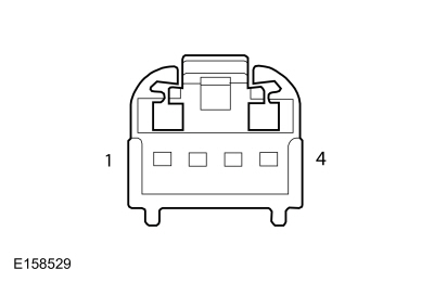 Steering Wheel Switch - Pin 2
|
|
Steering Wheel Switch - Pin 3
|
Is the voltage approximately 5 volts?
|
| T5
CHECK THE MESSAGE CENTER SWITCH SIGNAL CIRCUIT BETWEEN THE LH (LEFT-HAND)
STEERING WHEEL SWITCH AND THE UPPER CLOCKSPRING FOR A SHORT TO GROUND
|
-
 WARNING:
Turn the ignition OFF and wait one minute to deplete the backup power supply. Failure to follow this instruction may result
in serious personal injury or death in the event of an accidental deployment.
Wait one minute. WARNING:
Turn the ignition OFF and wait one minute to deplete the backup power supply. Failure to follow this instruction may result
in serious personal injury or death in the event of an accidental deployment.
Wait one minute.
-
Remove the driver airbag.
REFER to:
Driver Airbag
(501-20B Supplemental Restraint System, Removal and Installation).
-
Using a diagnostic scan tool, perform the
self-test.
Is
B137F:17 recorded?
|
| T6
CHECK THE MESSAGE CENTER SWITCH FOR A SHORT TO GROUND
|
-
Disconnect
Steering Wheel Switch C2998
.
-
Measure:
|
Positive Lead
|
Measurement / Action
|
Negative Lead
|
|
Steering Wheel Switch - Pin 2
|
|
Ground
|
Is the resistance greater than 10,000 ohms?
| No
|
INSTALL a new airbag.
REFER to:
Driver Airbag
(501-20B Supplemental Restraint System, Removal and Installation).
|
|
| T7
CHECK THE STEERING WHEEL SWITCH HARNESS FOR A SHORT TO GROUND
|
-
Disconnect Upper Clockspring C218B
.
-
Using a diagnostic scan tool, perform the
self-test.
Is
B137F:17 recorded?
| Yes
|
INSTALL a new steering wheel.
REFER to:
Steering Wheel
(211-04 Steering Column, Removal and Installation).
|
|
| T8
CHECK THE CLOCKSPRING FOR A SHORT TO GROUND
|
-
Remove clockspring from the
.
-
Using a diagnostic scan tool, perform the
self-test.
Is
B137F:17 recorded?
| Yes
|
INSTALL a new clockspring.
REFER to:
Clockspring
(501-20B Supplemental Restraint System, Removal and Installation).
|
|
| T9
CHECK THE MESSAGE CENTER SWITCH SIGNAL CIRCUIT FOR A SHORT TO VOLTAGE
|
-
WARNING:
Turn the ignition OFF and wait one minute to deplete the backup power supply. Failure to follow this instruction may result
in serious personal injury or death in the event of an accidental deployment.
Wait one minute.
-
Remove the driver airbag.
REFER to:
Driver Airbag
(501-20B Supplemental Restraint System, Removal and Installation).
-
Disconnect
Steering Wheel Switch C2998
.
-
Connect airbag to steering wheel inline.
-
Measure:
|
Positive Lead
|
Measurement / Action
|
Negative Lead
|
|
Steering Wheel Switch - Pin 2
|
|
Steering Wheel Switch - Pin 3
|
Is any voltage present?
|
| T10
CHECK THE MESSAGE CENTER SWITCH SIGNAL THROUGH THE AIRBAG FOR AN OPEN
|
-
Disconnect airbag to steering wheel inline.
-
Measure:
|
Positive Lead
|
Measurement / Action
|
Negative Lead
|
|
Steering Wheel Switch - Pin 2
|
|
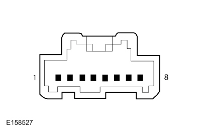 Steering Wheel to Airbag Inline - Pin 2 (Airbag Harness Side)
|
Is the resistance less than 3 ohms?
| No
|
INSTALL a new airbag.
REFER to:
Driver Airbag
(501-20B Supplemental Restraint System, Removal and Installation).
|
|
| T11
CHECK THE MESSAGE CENTER SWITCH SIGNAL CIRCUIT THROUGH THE STEERING WHEEL FOR AN OPEN
|
-
Disconnect Upper Clockspring C218B
.
-
Measure:
|
Positive Lead
|
Measurement / Action
|
Negative Lead
|
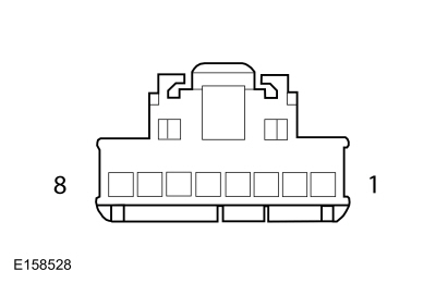 Steering Wheel to Airbag Inline - Pin 2 (Steering Wheel Harness Side)
|
|
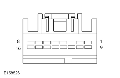 Clockspring - Pin 14 (Steering Wheel Harness Side)
|
Is the resistance less than 3 ohms?
|
| T12
CHECK THE MESSAGE CENTER SWITCH RETURN CIRCUIT THROUGH THE AIRBAG FOR AN OPEN
|
-
Measure:
|
Positive Lead
|
Measurement / Action
|
Negative Lead
|
|
Steering Wheel Switch - Pin 3
|
|
Steering Wheel to Airbag Inline - Pin 4 (Airbag Harness Side)
|
Is the resistance less than 3 ohms?
|
| T13
CHECK THE MESSAGE CENTER SWITCH RETURN CIRCUIT THROUGH THE STEERING WHEEL FOR AN OPEN
|
-
Measure:
|
Positive Lead
|
Measurement / Action
|
Negative Lead
|
|
Steering Wheel to Airbag Inline - Pin 4 (Steering Wheel Harness Side)
|
|
Clockspring - Pin 8 (Steering Wheel Harness Side)
|
Is the resistance less than 3 ohms?
|
| T14
CHECK THE MESSAGE CENTER SWITCH SIGNAL CIRCUIT THROUGH THE CLOCKSPRING FOR AN OPEN
|
-
Remove clockspring from the
.
-
Measure:
|
Positive Lead
|
Measurement / Action
|
Negative Lead
|
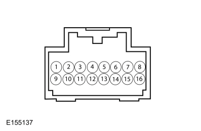 Upper Clockspring (Component Side) - Pin 14
|
|
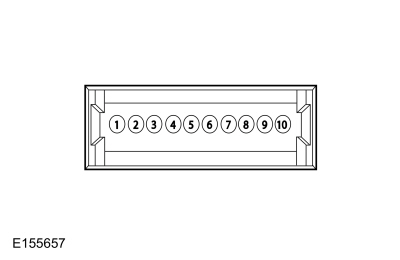 Lower Clockspring (Component Side) - Pin 6
|
Is the resistance less than 3 ohms?
| No
|
INSTALL a new clockspring.
REFER to:
Clockspring
(501-20B Supplemental Restraint System, Removal and Installation).
|
|
| T15
CHECK THE MESSAGE CENTER SWITCH RETURN CIRCUIT THROUGH THE CLOCKSPRING FOR AN OPEN
|
-
Measure:
|
Positive Lead
|
Measurement / Action
|
Negative Lead
|
|
Upper Clockspring (Component Side) - Pin 8
|
|
Lower Clockspring (Component Side) - Pin 9
|
Is the resistance less than 3 ohms?
| No
|
INSTALL a new clockspring.
REFER to:
Clockspring
(501-20B Supplemental Restraint System, Removal and Installation).
|
|
| T16
CHECK FOR CORRECT SCCM (STEERING COLUMN CONTROL MODULE)
OPERATION
|
-
Disconnect and inspect all the
connectors.
-
Repair:
-
corrosion (install new connector or terminals – clean module pins)
-
damaged or bent pins – install new terminals/pins
-
pushed-out pins – install new pins as necessary
-
Reconnect all the
connectors. Make sure they seat and latch correctly.
-
Operate the system and determine if the concern is still present.
Is the concern still present?
| Yes
|
CHECK On-Line Automotive Service Information System (OASIS) for any applicable Technical Service Bulletins (TSBs). If a
exists for this concern, DISCONTINUE this test and FOLLOW
instructions. If no Technical Service Bulletins (TSBs) address this concern, INSTALL a new
.
REFER to:
Steering Column Control Module (SCCM)
(211-05 Steering Wheel and Column Electrical Components, Removal and Installation).
|
| No
|
The system is operating correctly at this time. The concern may have been caused by module connections. ADDRESS the root cause
of any connector or pin issues.
|
|
The Compass Is Inoperative
Normal Operation and Fault Conditions
See Compass Display.
REFER to:
Message Center - System Operation and Component Description
(413-01 Instrumentation, Message Center and Warning Chimes, Description and Operation).
If the compass display data messages are missing or invalid for 5 seconds or less, the compass displays the last vehicle direction
based upon the last known good compass display message received.
If the compass display data messages are invalid or missing for more than 5 seconds, the
defaults the display to all dashes (---).
Possible Sources
-
Communication concern
-
concern
-
PINPOINT TEST U : THE COMPASS IS INOPERATIVE
| U1
RETRIEVE THE RECORD DIAGNOSTIC TROUBLE CODES (DTCS) FROM THE GPSM (GLOBAL POSITIONING SYSTEM MODULE)
SELF-TEST
|
-
Using a diagnostic scan tool, perform the
self-test.
Are any Diagnostic Trouble Codes (DTCs) recorded?
| Yes
|
If equipped with the touchscreen audio system,
REFER to:
Information and Entertainment System
(415-00A Information and Entertainment System - General Information - Vehicles With: Touchscreen Display, Diagnosis and Testing).
If equipped with the THX® audio system,
REFER to:
Information and Entertainment System
(415-00B Information and Entertainment System - General Information - Vehicles With: THX Audio System, Diagnosis and Testing).
|
|
| U2
RETRIEVE THE RECORD DIAGNOSTIC TROUBLE CODES (DTCS) FROM THE IPC (INSTRUMENT PANEL CLUSTER)
SELF-TEST
|
-
Using a diagnostic scan tool, perform the
self-test.
Are any Diagnostic Trouble Codes (DTCs) recorded?
| Yes
|
REFER to
Chart:
in this section.
|
| No
|
INSTALL a new
.
If equipped with the touchscreen audio system,
REFER to:
Global Positioning System Module (GPSM)
(415-00A Information and Entertainment System - General Information - Vehicles With: Touchscreen Display, Removal and Installation).
If equipped with the THX® audio system,
REFER to:
Global Positioning System Module (GPSM)
(415-00B Information and Entertainment System - General Information - Vehicles With: THX Audio System, Removal and Installation).
|
|
The Outside Air Temperature Display Is Inoperative or Incorrect
Normal Operation and Fault Conditions
See Outside Air Temperature Display.
REFER to:
Message Center - System Operation and Component Description
(413-01 Instrumentation, Message Center and Warning Chimes, Description and Operation).
If the air ambient temperature message is missing or invalid for less than 5 seconds, the
defaults the outside air temperature display to the last temperature reading, based upon the last message received.
If the air ambient temperature message is missing or invalid for 5 seconds or longer from the
, the
displays all dashes (- - - -) in the outside air temperature display area.
Possible Sources
-
Communication concern
-
Ambient Air Temperature (AAT) sensor input to the
-
concern
PINPOINT TEST V : THE OUTSIDE AIR TEMPERATURE DISPLAY IS INOPERATIVE OR INCORRECT
| V1
PERFORM THE IPC (INSTRUMENT PANEL CLUSTER)
SELF-TEST
|
-
Using a diagnostic scan tool, perform the
self-test.
Are any Diagnostic Trouble Codes (DTCs) recorded?
| Yes
|
REFER to
Chart:
in this section.
|
|
| V2
PERFORM THE BCM (BODY CONTROL MODULE)
SELF-TEST
|
-
Using a diagnostic scan tool, perform the
self-test.
Are any Diagnostic Trouble Codes (DTCs) recorded?
|
| V3
PERFORM THE PCM (POWERTRAIN CONTROL MODULE)
SELF-TEST
|
-
Using a diagnostic scan tool, perform the
self-test.
Are any Diagnostic Trouble Codes (DTCs) recorded?
| Yes
|
Refer to the appropriate section in Group 303 for the procedure.
|
| No
|
DIAGNOSE all ambient temperature related Diagnostic Trouble Codes (DTCs) in the
. Refer to the appropriate section in Group 303 for the procedure.
|
|
The Blind Spot Information System (BLIS®) Off Message Center Indicator Is Never Or Always On
Normal Operation and Fault Conditions
See Blind Spot Monitoring System (BLIS®) Off Message Center Indicator.
REFER to:
Message Center - System Operation and Component Description
(413-01 Instrumentation, Message Center and Warning Chimes, Description and Operation).
If the cross traffic alert left or cross traffic right message is missing or invalid for less than 5 seconds, the
defaults the Blind Spot Information System (BLIS®) off message center indicator to the last state (on or off), based upon
the last message received.
If the cross traffic alert left or cross traffic right message is missing or invalid for 5 seconds or longer, the
defaults the Blind Spot Information System (BLIS®) off message center warning indicator off.
Possible Sources
-
Communication concern
-
concern
-
concern
-
PINPOINT TEST W : THE BLIND SPOT INFORMATION SYSTEM (BLIS®) OFF MESSAGE CENTER INDICATOR IS NEVER OR ALWAYS ON
| W1
CHECK THE MESSAGE CENTER OPERATION
|
-
Close all doors, the hood and luggage compartment lid.
-
Clear all message center warnings by pressing the OK button for each warning present.
-
Monitor the door ajar message center warning indicator.
-
Clear the message center popup warning.
-
Monitor the door ajar message center warning indicator.
Is the door ajar message center warning indicator off with the door closed, and on with the door open?
|
| W2
PERFORM THE IPC (INSTRUMENT PANEL CLUSTER)
SELF-TEST
|
-
Using a diagnostic scan tool, perform the
self-test.
Are any Diagnostic Trouble Codes (DTCs) recorded?
| Yes
|
REFER to
Chart:
in this section.
|
|
| W3
PERFORM THE SODL (SIDE OBSTACLE DETECTION CONTROL MODULE LH)
AND SODR (SIDE OBSTACLE DETECTION CONTROL MODULE RH)
SELF-TESTS
|
-
Using a diagnostic scan tool, perform the
and
self-tests.
Are any Diagnostic Trouble Codes (DTCs) recorded?
|
| W4
CHECK THE GWM (GATEWAY MODULE A)
DIAGNOSTIC TROUBLE CODES (DTCS)
|
-
Using a diagnostic scan tool, check the
Continuous Memory Diagnostic Trouble Codes (CMDTCs).
Are any Diagnostic Trouble Codes (DTCs) recorded?
| No
|
DIAGNOSE the Blind Spot Information System (BLIS).
REFER to:
Blind Spot Information System
(419-04 Side and Rear Vision, Diagnosis and Testing).
|
|
The Charging System Message Center Warning Indicator Is Never Or Always On
Normal Operation and Fault Conditions
See Charging System Message Center Indicator.
REFER to:
Message Center - System Operation and Component Description
(413-01 Instrumentation, Message Center and Warning Chimes, Description and Operation).
If the charging system indication request is missing for less than 5 seconds, the
defaults the charging system message center indicator to the last indication state (on or off), based upon on the last message
received.
If the charging system indication request is missing for 5 seconds or longer, the
defaults the charging system message center indicator on.
Possible Sources
-
Charging system concern
-
Communication concern
-
PINPOINT TEST X : THE CHARGING SYSTEM MESSAGE CENTER WARNING INDICATOR IS NEVER OR ALWAYS ON
| X1
CHECK THE MESSAGE CENTER OPERATION
|
-
Close all doors, the hood and luggage compartment lid.
-
Clear all message center warnings by pressing the OK button for each warning present.
-
Monitor the door ajar message center warning indicator.
-
Clear the message center popup warning.
-
Monitor the door ajar message center warning indicator.
Is the door ajar message center warning indicator off with the door closed, and on with the door open?
|
| X2
PERFORM THE IPC (INSTRUMENT PANEL CLUSTER)
SELF-TEST
|
-
Using a diagnostic scan tool, perform the
self-test.
Are any Diagnostic Trouble Codes (DTCs) recorded?
| Yes
|
REFER to
Chart:
in this section.
|
|
| X3
CHECK THE GWM (GATEWAY MODULE A)
DIAGNOSTIC TROUBLE CODES (DTCS)
|
-
Using a diagnostic scan tool, check the
Continuous Memory Diagnostic Trouble Codes (CMDTCs).
Are any Diagnostic Trouble Codes (DTCs) recorded?
|
| X4
CHECK THE CHARGING SYSTEM OPERATION
|
-
Check the charging system operation.
Does the charging system operate correctly?
| Yes
|
If the charging system warning indicator is never on, the system is operating correctly at this time.
If the charging system warning indicator is always on, DIAGNOSE all
Diagnostic Trouble Codes (DTCs).
REFER to:
Body Control Module (BCM)
(419-10 Multifunction Electronic Modules, Diagnosis and Testing).
|
| No
|
REFER to:
Charging System
(414-00 Charging System - General Information, Diagnosis and Testing).
|
|
The Cruise Control Message Center Indicator Is Never On
Normal Operation and Fault Conditions
See Cruise Control Message Center Indicator.
REFER to:
Message Center - System Operation and Component Description
(413-01 Instrumentation, Message Center and Warning Chimes, Description and Operation).
If the cruise control status, cruise control override (adaptive cruise) or cruise control set speed (adaptive cruise) message
is missing or deemed invalid by the
for less than 5 seconds, the
defaults the cruise control indicator to the last indication state (on or off), based upon the last message received.
If the cruise control status, cruise control override (adaptive cruise) or cruise control set speed (adaptive cruise) message
is missing or if the data is deemed invalid by the
for 5 seconds or longer, the
defaults the cruise control indicator off.
Possible Sources
-
Communication concern
-
Cruise control concern
-
PINPOINT TEST Y : THE CRUISE CONTROL MESSAGE CENTER INDICATOR IS NEVER ON
| Y1
CHECK THE MESSAGE CENTER OPERATION
|
-
Close all doors, the hood and luggage compartment lid.
-
Clear all message center warnings by pressing the OK button for each warning present.
-
Monitor the door ajar message center warning indicator.
-
Clear the message center popup warning.
-
Monitor the door ajar message center warning indicator.
Is the door ajar message center warning indicator off with the door closed, and on with the door open?
|
| Y2
PERFORM THE IPC (INSTRUMENT PANEL CLUSTER)
SELF-TEST
|
-
Using a diagnostic scan tool, perform the
self-test.
Are any Diagnostic Trouble Codes (DTCs) recorded?
| Yes
|
REFER to
Chart:
in this section.
|
|
| Y3
CHECK THE GWM (GATEWAY MODULE A)
DIAGNOSTIC TROUBLE CODES (DTCS)
|
-
Using a diagnostic scan tool, check the
Continuous Memory Diagnostic Trouble Codes (CMDTCs).
Are any Diagnostic Trouble Codes (DTCs) recorded?
| No
|
DIAGNOSE the cruise control system.
REFER to:
Cruise Control
(419-03A Cruise Control, Diagnosis and Testing).
|
|
The Door Ajar, Hood Ajar or Luggage Compartment Lid Ajar Message Center Warning Indicator Is Never On
Refer to Wiring Diagrams Cell 89 for schematic and connector information.
Normal Operation and Fault Conditions
See Door Ajar Indication Message Center Displays.
REFER to:
Message Center - System Operation and Component Description
(413-01 Instrumentation, Message Center and Warning Chimes, Description and Operation).
If the door status message is missing for less than 5 seconds, the
defaults all door, hood and luggage compartment lid ajar message center displays to the last indication state (on or off),
based upon the last message received.
If the door status message is missing for 5 seconds or longer, the
defaults all door, hood and luggage compartment lid ajar message center displays off.
Fault Trigger Conditions
|
DTC
|
Description
|
Fault Trigger Conditions
|
|
B1306:11
|
Liftgate Ajar Switch: Circuit Short To Ground
|
A continuous and on-demand
that sets in the
if the
detects the luggage compartment lid ajar output circuit short to ground for longer than 5 seconds.
|
Possible Sources
-
Wiring, terminals or connectors
-
Interior lighting concern
-
Luggage compartment lid latch ajar switch (part of the luggage compartment lid latch)
-
Communication concern
-
concern
-
(power luggage compartment lid)
-
PINPOINT TEST Z : THE DOOR AJAR MESSAGE CENTER WARNING INDICATOR IS NEVER ON
| Z1
CHECK THE MESSAGE CENTER OPERATION
|
-
Monitor the message center messages and message center indicators.
Did multiple message center messages and message center warning indicators appear?
|
| Z2
CHECK THE INTERIOR LIGHTING OPERATION
|
-
Open and close each door while monitoring the interior lamps.
Do the interior lamps operate correctly with each door?
|
| Z3
PERFORM THE IPC (INSTRUMENT PANEL CLUSTER)
SELF-TEST
|
-
Using a diagnostic scan tool, perform the
self-test.
Are any Diagnostic Trouble Codes (DTCs) recorded?
| Yes
|
REFER to
Chart:
in this section.
|
|
| Z4
CHECK THE GWM (GATEWAY MODULE A)
DIAGNOSTIC TROUBLE CODES (DTCS)
|
-
Using a diagnostic scan tool, check the
Continuous Memory Diagnostic Trouble Codes (CMDTCs).
Are any Diagnostic Trouble Codes (DTCs) recorded?
|
| Z5
PERFORM THE BCM (BODY CONTROL MODULE)
SELF-TEST
|
-
Using a diagnostic scan tool, perform the
self-test.
Are any Diagnostic Trouble Codes (DTCs) recorded?
| No
|
For a hood ajar indication concern, DIAGNOSE the perimeter alarm.
REFER to:
Perimeter Anti-Theft Alarm
(419-01A Perimeter Anti-Theft Alarm, Diagnosis and Testing).
For a luggage compartment lid indication concern, GO to
Z6
|
|
| Z6
CHECK THE LUGGAGE COMPARTMENT LID RELEASE FUNCTION
|
-
Verify the luggage compartment lid release function operates.
Does the luggage compartment lid release?
|
| Z7
CHECK THE LUGGAGE COMPARTMENT AJAR SWITCH FOR A SHORT TO GROUND
|
-
Disconnect Luggage Compartment Lid Latch C4424
.
-
Monitor the luggage compartment lid ajar message center indicator.
Does the luggage compartment lid ajar message center indicator turn on?
| Yes
|
INSTALL a new luggage compartment lid latch.
REFER to:
Luggage Compartment Lid Latch
(501-14 Handles, Locks, Latches and Entry Systems, Removal and Installation).
|
| No
|
For a luggage compartment lid indication concern without power luggage compartment lid, GO to
Z10
For a luggage compartment lid indication concern with power luggage compartment lid, GO to
Z8
|
|
| Z8
CHECK THE LUGGAGE COMPARTMENT AJAR INPUT FOR A SHORT TO GROUND
|
-
Monitor the luggage compartment lid ajar message center indicator.
Does the luggage compartment lid ajar message center indicator turn on?
|
| Z9
CHECK THE LUGGAGE COMPARTMENT AJAR INPUT FOR A SHORT TO GROUND AT THE RGTM (REAR GATE TRUNK MODULE)
|
-
Measure:
|
Positive Lead
|
Measurement / Action
|
Negative Lead
|
|
C4174B-2
|
|
Ground
|
Is the resistance greater than 10,000 ohms?
|
| Z10
CHECK THE LUGGAGE COMPARTMENT AJAR INPUT CIRCUIT FOR A SHORT TO GROUND AT THE BCM (BODY CONTROL MODULE)
|
-
Measure:
|
Positive Lead
|
Measurement / Action
|
Negative Lead
|
|
C2280D-34
|
|
Ground
|
Is the resistance greater than 10,000 ohms?
|
| Z11
CHECK FOR CORRECT BCM (BODY CONTROL MODULE)
OPERATION
|
-
Disconnect and inspect all
connectors.
-
Repair:
-
corrosion (install new connector or terminals – clean module pins)
-
damaged or bent pins – install new terminals/pins
-
pushed-out pins – install new pins as necessary
-
Reconnect the
connectors. Make sure they seat and latch correctly.
-
Operate the system and determine if the concern is still present.
Is the concern still present?
| Yes
|
CHECK
for any applicable Technical Service Bulletins (TSBs). If a
exists for this concern, DISCONTINUE this test and FOLLOW
instructions. If no Technical Service Bulletins (TSBs) address this concern, INSTALL a new
.
REFER to:
Body Control Module (BCM)
(419-10 Multifunction Electronic Modules, Removal and Installation).
|
| No
|
The system is operating correctly at this time. The concern may have been caused by module connections. ADDRESS the root cause
of any connector or pin issues.
|
|
| Z12
CHECK FOR CORRECT RGTM (REAR GATE TRUNK MODULE)
OPERATION
|
-
Disconnect and inspect all
connectors.
-
Repair:
-
corrosion (install new connector or terminals – clean module pins)
-
damaged or bent pins – install new terminals/pins
-
pushed-out pins – install new pins as necessary
-
Reconnect the
connectors. Make sure they seat and latch correctly.
-
Operate the system and determine if the concern is still present.
Is the concern still present?
| Yes
|
CHECK
for any applicable Technical Service Bulletins (TSBs). If a
exists for this concern, DISCONTINUE this test and FOLLOW
instructions. If no Technical Service Bulletins (TSBs) address this concern, INSTALL a new
.
REFER to:
Rear Gate Trunk Module (RGTM)
(501-03 Body Closures, Removal and Installation).
|
| No
|
The system is operating correctly at this time. The concern may have been caused by module connections. ADDRESS the root cause
of any connector or pin issues.
|
|
The Door Ajar, Hood Ajar or Luggage Compartment Lid Ajar Message Center Warning Indicator Is Always On
Refer to Wiring Diagrams Cell 89 for schematic and connector information.
Normal Operation and Fault Conditions
See Door Ajar Indication Message Center Displays.
REFER to:
Message Center - System Operation and Component Description
(413-01 Instrumentation, Message Center and Warning Chimes, Description and Operation).
If the door status message is missing for less than 5 seconds, the
defaults all door, hood and luggage compartment lid ajar message center displays to the last indication state (on or off),
based upon the last message received.
If the door status message is missing for 5 seconds or longer, the
defaults all door, hood and luggage compartment lid ajar message center displays off.
Fault Trigger Conditions
|
DTC
|
Description
|
Fault Trigger Conditions
|
|
B1178:01
|
Boot/Trunk Ajar Switch: General Electrical Failure
|
An on-demand
that sets in the
if the
detects an open or short to voltage on the luggage compartment lid ajar input.
|
Fault Trigger Conditions
|
DTC
|
Description
|
Fault Trigger Conditions
|
|
B1306:12
|
Liftgate Ajar Switch: Circuit Short To Battery
|
A continuous and on-demand
that sets in the
if the
detects the luggage compartment lid ajar output circuit open or short to voltage for longer than 5 seconds.
|
Possible Sources
-
Wiring, terminals or connectors
-
Interior lighting concern
-
Luggage compartment lid latch ajar switch (part of the luggage compartment lid latch)
-
concern
-
(power luggage compartment lid)
PINPOINT TEST AA : THE DOOR AJAR MESSAGE CENTER WARNING INDICATOR IS ALWAYS ON
| AA1
CHECK THE INTERIOR LIGHTING OPERATION
|
-
Open and close each door while monitoring the interior lamps.
Do the interior lamps operate correctly with each door?
| Yes
|
For the hood ajar indication concern, DIAGNOSE the perimeter alarm.
REFER to:
Perimeter Anti-Theft Alarm
(419-01A Perimeter Anti-Theft Alarm, Diagnosis and Testing).
For a luggage compartment lid ajar indication concern, GO to
AA2
|
|
| AA2
CHECK THE LUGGAGE COMPARTMENT LID RELEASE FUNCTION
|
-
Verify the luggage compartment lid release function operates.
Does the luggage compartment lid release?
|
| AA3
CHECK THE LUGGAGE COMPARTMENT LID AJAR SWITCH INPUT
|
-
Disconnect Luggage Compartment Lid Latch C4424
.
-
NOTE:
If the fused jumper wire fails, repair the luggage compartment lid ajar input circuit for a short to voltage.
Connect:
|
Lead 1
|
Measurement / Action
|
Lead 2
|
|
C4424-1
|
|
C4424-4
|
-
Monitor the luggage compartment lid latch message center warning indicator.
Does the luggage compartment lid latch message center indicator turn off?
| Yes
|
REMOVE the fused jumper wire. INSTALL a new luggage compartment latch.
REFER to:
Luggage Compartment Lid Latch
(501-14 Handles, Locks, Latches and Entry Systems, Removal and Installation).
|
| No
|
For a luggage compartment lid indication concern without power luggage compartment lid, LEAVE the fused jumper wire connected.
GO to
AA4
For a luggage compartment lid indication concern with power luggage compartment lid, LEAVE the fused jumper wire connected.
GO to
AA5
|
|
| AA4
CHECK THE LUGGAGE COMPARTMENT LID AJAR INPUT CIRCUIT FOR AN OPEN AT THE BCM (BODY CONTROL MODULE)
|
-
Measure:
|
Positive Lead
|
Measurement / Action
|
Negative Lead
|
|
C2280D-34
|
|
Ground
|
Is the resistance less than 3 ohms?
| Yes
|
REMOVE the fused jumper wire. GO to
AA8
|
| No
|
REMOVE the fused jumper wire. REPAIR the circuit.
|
|
| AA5
CHECK THE LUGGAGE COMPARTMENT LID AJAR INPUT CIRCUIT FOR AN OPEN AT THE RGTM (REAR GATE TRUNK MODULE)
|
-
Measure:
|
Positive Lead
|
Measurement / Action
|
Negative Lead
|
|
C4174B-2
|
|
Ground
|
Is the resistance less than 3 ohms?
| Yes
|
REMOVE the fused jumper wire. GO to
AA6
|
| No
|
REMOVE the fused jumper wire. REPAIR the circuit.
|
|
| AA6
BYPASS THE LUGGAGE COMPARTMENT LID AJAR SWITCH INPUT AT THE RGTM (REAR GATE TRUNK MODULE)
|
-
Connect:
|
Lead 1
|
Measurement / Action
|
Lead 2
|
|
C4174B-15
|
|
Ground
|
-
Monitor the luggage compartment lid ajar message center warning indicator.
Does the luggage compartment lid latch message center indicator turn off?
| Yes
|
REMOVE the fused jumper wire. GO to
AA9
|
| No
|
REMOVE the fused jumper wire. GO to
AA7
|
|
| AA7
CHECK THE LUGGAGE COMPARTMENT AJAR INPUT CIRCUIT FOR AN OPEN BETWEEN THE RGTM (REAR GATE TRUNK MODULE)
AND THE BCM (BODY CONTROL MODULE)
|
-
Measure:
|
Positive Lead
|
Measurement / Action
|
Negative Lead
|
|
C4174B-15
|
|
C2280D-34
|
Is the resistance less than 3 ohms?
|
| AA8
CHECK FOR CORRECT BCM (BODY CONTROL MODULE)
OPERATION
|
-
Disconnect and inspect all
connectors.
-
Repair:
-
corrosion (install new connector or terminals – clean module pins)
-
damaged or bent pins – install new terminals/pins
-
pushed-out pins – install new pins as necessary
-
Reconnect the
connectors. Make sure they seat and latch correctly.
-
Operate the system and determine if the concern is still present.
Is the concern still present?
| Yes
|
CHECK
for any applicable Technical Service Bulletins (TSBs). If a
exists for this concern, DISCONTINUE this test and FOLLOW
instructions. If no Technical Service Bulletins (TSBs) address this concern, INSTALL a new
.
REFER to:
Body Control Module (BCM)
(419-10 Multifunction Electronic Modules, Removal and Installation).
|
| No
|
The system is operating correctly at this time. The concern may have been caused by module connections. ADDRESS the root cause
of any connector or pin issues.
|
|
| AA9
CHECK FOR CORRECT RGTM (REAR GATE TRUNK MODULE)
OPERATION
|
-
Disconnect and inspect all
connectors.
-
Repair:
-
corrosion (install new connector or terminals – clean module pins)
-
damaged or bent pins – install new terminals/pins
-
pushed-out pins – install new pins as necessary
-
Reconnect the
connectors. Make sure they seat and latch correctly.
-
Operate the system and determine if the concern is still present.
Is the concern still present?
| Yes
|
CHECK
for any applicable Technical Service Bulletins (TSBs). If a
exists for this concern, DISCONTINUE this test and FOLLOW
instructions. If no Technical Service Bulletins (TSBs) address this concern, INSTALL a new
.
REFER to:
Rear Gate Trunk Module (RGTM)
(501-03 Body Closures, Removal and Installation).
|
| No
|
The system is operating correctly at this time. The concern may have been caused by module connections. ADDRESS the root cause
of any connector or pin issues.
|
|
The Engine Over-Temperature Message Center Warning Indicator Is Never Or Always On
Normal Operation and Fault Conditions
See Engine Over-Temperature Message Center Warning Indicator.
REFER to:
Message Center - System Operation and Component Description
(413-01 Instrumentation, Message Center and Warning Chimes, Description and Operation).
If the engine coolant temperature data, engine overheat indication request or
heater core temperature messages are missing or invalid for less than 5 seconds, the
defaults the motor over-temperature message center warning indicator to the last indication state (on or off), based upon
on the last message received.
If the engine coolant temperature data, engine overheat indication request or
heater core temperature messages are missing or invalid for 5 seconds or longer, the
defaults the motor over-temperature message center warning indicator on.
Possible Sources
-
Communication concern
-
input concern
-
PINPOINT TEST AB : THE ENGINE OVER-TEMPERATURE MESSAGE CENTER WARNING INDICATOR IS NEVER OR ALWAYS ON
| AB1
CHECK THE MESSAGE CENTER OPERATION
|
-
Close all doors, the hood and luggage compartment lid.
-
Clear all message center warnings by pressing the OK button for each warning present.
-
Monitor the door ajar message center warning indicator.
-
Clear the message center popup warning.
-
Monitor the door ajar message center warning indicator.
Is the door ajar message center warning indicator off with the door closed, and on with the door open?
|
| AB2
PERFORM THE IPC (INSTRUMENT PANEL CLUSTER)
SELF-TEST
|
-
Using a diagnostic scan tool, perform the
self-test.
Are any Diagnostic Trouble Codes (DTCs) recorded?
| Yes
|
REFER to
Chart:
in this section.
|
|
| AB3
CHECK THE GWM (GATEWAY MODULE A)
DIAGNOSTIC TROUBLE CODES (DTCS)
|
-
Using a diagnostic scan tool, check the
Continuous Memory Diagnostic Trouble Codes (CMDTCs).
Are any Diagnostic Trouble Codes (DTCs) recorded?
| No
|
If the engine over-temperature message center is never on, the system is operating correctly at this time.
If the engine over-temperature message center indicator is always on, DIAGNOSE all
Diagnostic Trouble Codes (DTCs).
For 3.7L engine,
REFER to:
Electronic Engine Controls
(303-14A Electronic Engine Controls - 3.7L Duratec (227kW/301PS), Diagnosis and Testing).
For 2.0L engine,
REFER to:
Electronic Engine Controls
(303-14B Electronic Engine Controls - 2.0L EcoBoost (184kW/250PS) - MI4, Diagnosis and Testing).
|
|
The Lane Departure On Message Center Indicator Is Never Or Always On
Normal Operation and Fault Conditions
See Hazard Message Center Warning Indicator.
REFER to:
Message Center - System Operation and Component Description
(413-01 Instrumentation, Message Center and Warning Chimes, Description and Operation).
If the lane departure warning indicator request is missing for less than 5 seconds, the
defaults the lane departure message center indicator to the last indication state (on or off), based upon the last message
received.
If the lane departure warning indicator request is missing for 5 seconds or longer, the
defaults the lane departure message center indicator off.
Possible Sources
-
Lane departure warning system concern
-
Communication concern
-
PINPOINT TEST AC : THE LANE DEPARTURE ON MESSAGE CENTER INDICATOR IS NEVER OR ALWAYS ON
| AC1
CHECK THE MESSAGE CENTER OPERATION
|
-
Close all doors, the hood and luggage compartment lid.
-
Clear all message center warnings by pressing the OK button for each warning present.
-
Monitor the door ajar message center warning indicator.
-
Clear the message center popup warning.
-
Monitor the door ajar message center warning indicator.
Is the door ajar message center warning indicator off with the door closed, and on with the door open?
|
| AC2
CHECK THE LANE DEPARTURE SWITCH OPERATION
|
-
Press the lane departure switch to turn the system on then off again.
Does the lane departure message center indicator turn on then off again?
| Yes
|
The system is operating correctly at this time. The system was turned off.
|
|
| AC3
PERFORM THE IPC (INSTRUMENT PANEL CLUSTER)
SELF-TEST
|
-
Using a diagnostic scan tool, perform the
self-test.
Are any Diagnostic Trouble Codes (DTCs) recorded?
| Yes
|
REFER to
Chart:
in this section.
|
|
| AC4
CHECK THE GWM (GATEWAY MODULE A)
DIAGNOSTIC TROUBLE CODES (DTCS)
|
-
Using a diagnostic scan tool, check the
Continuous Memory Diagnostic Trouble Codes (CMDTCs).
Are any Diagnostic Trouble Codes (DTCs) recorded?
| No
|
DIAGNOSE the lane departure warning system.
REFER to:
Lane Departure Warning
(419-07 Lane Departure Warning, Diagnosis and Testing).
|
|
The Low Fuel Message Center Warning Indicator Is Never Or Always On
Normal Operation and Fault Conditions
See Low Fuel Message Center Warning Indicator.
REFER to:
Message Center - System Operation and Component Description
(413-01 Instrumentation, Message Center and Warning Chimes, Description and Operation).
Possible Sources
PINPOINT TEST AD : THE LOW FUEL MESSAGE CENTER WARNING INDICATOR IS NEVER OR ALWAYS ON
| AD1
CHECK THE MESSAGE CENTER OPERATION
|
-
Close all doors, the hood and luggage compartment lid.
-
Clear all message center warnings by pressing the OK button for each warning present.
-
Monitor the door ajar message center warning indicator.
-
Clear the message center popup warning.
-
Monitor the door ajar message center warning indicator.
Is the door ajar message center warning indicator off with the door closed, and on with the door open?
|
| AD2
VERIFY THE OPERATION OF THE FUEL GAUGE
|
-
Verify the fuel gauge operates correctly and there are no customer concerns with the fuel gauge operation.
Does the fuel gauge operate correctly without any customer concerns related to fuel gauge indication?
|
| AD3
CONFIRM THE CURRENT FUEL LEVEL
|
-
Scroll to the
Inst Fuel1
display.
Does the FLPM (second value) indicate 104 or less with an administrator key or between 104 and 164 with a MyKey® programmed
key?
| Yes
|
If the low fuel message center warning indicator is always on, the system is operating correctly at this time based on the
current fuel level.
If the low fuel message center warning indicator is never on, INSTALL a new
.
REFER to:
Instrument Panel Cluster (IPC)
(413-01 Instrumentation, Message Center and Warning Chimes, Removal and Installation).
|
| No
|
If the low fuel message center warning indicator is always on, INSTALL a new
.
REFER to:
Instrument Panel Cluster (IPC)
(413-01 Instrumentation, Message Center and Warning Chimes, Removal and Installation).
If the low fuel message center warning indicator is never on, the system is operating correctly at this time based on the
current fuel level.
|
|
The Low Oil Pressure Message Center Warning Indicator Is Never Or Always On
Refer to Wiring Diagrams Cell 60 for schematic and connector information.
Normal Operation and Fault Conditions
See Low Oil Pressure Message Center Warning Indicator.
REFER to:
Message Center - System Operation and Component Description
(413-01 Instrumentation, Message Center and Warning Chimes, Description and Operation).
If the engine rpm data or oil pressure warning message is missing less than 5 seconds, the
defaults the low oil pressure warning indicator to the last state (on or off), based upon the last message received.
If the engine rpm data or oil pressure warning message is missing for 5 seconds or longer, the
defaults the low oil pressure warning indicator on.
Possible Sources
-
Wiring, terminals or connectors
-
Tachometer concern
-
Engine oil pressure switch
-
Base engine concern
-
concern
-
PINPOINT TEST AE : THE LOW OIL PRESSURE MESSAGE CENTER WARNING INDICATOR IS NEVER OR ALWAYS ON
| AE1
CHECK THE MESSAGE CENTER OPERATION
|
-
Close all doors, the hood and luggage compartment lid.
-
Clear all message center warnings by pressing the OK button for each warning present.
-
Monitor the door ajar message center warning indicator.
-
Clear the message center popup warning.
-
Monitor the door ajar message center warning indicator.
Is the door ajar message center warning indicator off with the door closed, and on with the door open?
|
| AE2
CHECK THE TACHOMETER OPERATION
|
-
NOTE:
For the dual 4.2" message center display
, make sure the
is set to display the tachometer. The
and message center navigation can be found in the Owner's Literature
Verify the tachometer operates.
Does the tachometer operate?
|
| AE3
PERFORM THE IPC (INSTRUMENT PANEL CLUSTER)
SELF-TEST
|
-
Using a diagnostic scan tool, perform the
self-test.
Are any Diagnostic Trouble Codes (DTCs) recorded?
| Yes
|
REFER to
Chart:
in this section.
|
| No
|
If the low oil pressure message center warning indicator is never on, GO to
AE4
If the low oil pressure message center warning indicator is always on, GO to
AE6
|
|
| AE4
CHECK FOR A STUCK CLOSED ENGINE OIL PRESSURE SWITCH
|
-
Disconnect Engine Oil Pressure Switch C103 (2.0L).
-
Disconnect Engine Oil Pressure Switch C1642 (3.7L).
-
Observe the low oil pressure warning indicator.
Does the low oil pressure warning indicator turn on?
| Yes
|
INSTALL a new engine oil pressure switch. Refer to the appropriate section in Group 303 for the procedure.
|
|
| AE5
CHECK THE OIL PRESSURE INPUT CIRCUIT FOR A SHORT TO GROUND AT THE PCM (POWERTRAIN CONTROL MODULE)
|
-
Disconnect
C1381E (2.0L).
-
Measure:
2.0L
|
Positive Lead
|
Measurement / Action
|
Negative Lead
|
|
C1381E-9
|
|
Ground
|
3.7L
|
Positive Lead
|
Measurement / Action
|
Negative Lead
|
|
C175E-13
|
|
Ground
|
Is the resistance greater than 10,000 ohms?
|
| AE6
CHECK THE GWM (GATEWAY MODULE A)
DIAGNOSTIC TROUBLE CODES (DTCS)
|
-
Using a diagnostic scan tool, check the
Continuous Memory Diagnostic Trouble Codes (CMDTCs).
Are any Diagnostic Trouble Codes (DTCs) recorded?
|
| AE7
PERFORM THE PCM (POWERTRAIN CONTROL MODULE)
SELF-TEST
|
-
Using a diagnostic scan tool, perform the
self-test.
Are any Diagnostic Trouble Codes (DTCs) recorded?
| Yes
|
Refer to Powertrain Control/Emissions Diagnosis (PC/ED) manual.
|
|
| AE8
CHECK FOR A STUCK OPEN ENGINE OIL PRESSURE SWITCH
|
-
Disconnect Engine Oil Pressure Switch C103 (2.0L).
-
Disconnect Engine Oil Pressure Switch C1642 (3.7L).
-
Connect:
2.0L
|
Lead 1
|
Measurement / Action
|
Lead 2
|
|
C103-1
|
|
Ground
|
3.7L
|
Lead 1
|
Measurement / Action
|
Lead 2
|
|
C1642-1
|
|
Ground
|
-
Observe the low oil pressure warning indicator.
Does the low oil pressure indicator turn off?
| Yes
|
REMOVE the fused jumper wire. GO to
AE9
|
| No
|
LEAVE the fused jumper wire connected. GO to
AE10
|
|
| AE9
CHECK THE OIL PRESSURE
|
-
Test the engine for low oil pressure.
Was a low oil pressure concern detected?
| Yes
|
REPAIR the low oil pressure concern. Refer to the appropriate section in Group 303 for the procedure.
|
| No
|
INSTALL a new engine oil pressure switch. Refer to the appropriate section in Group 303 for the procedure.
|
|
| AE10
CHECK THE ENGINE OIL PRESSURE INPUT CIRCUIT FOR AN OPEN AT THE PCM (POWERTRAIN CONTROL MODULE)
|
-
Disconnect
C1381E (2.0L).
-
Measure:
2.0L
|
Positive Lead
|
Measurement / Action
|
Negative Lead
|
|
C1381E-9
|
|
Ground
|
3.7L
|
Positive Lead
|
Measurement / Action
|
Negative Lead
|
|
C175E-13
|
|
Ground
|
Is the resistance less than 3 ohms?
| Yes
|
REMOVE the fused jumper wire. GO to
AE11
|
| No
|
REMOVE the fused jumper wire. REPAIR the circuit.
|
|
| AE11
CHECK FOR CORRECT PCM (POWERTRAIN CONTROL MODULE)
OPERATION
|
-
Disconnect and inspect all
connectors.
-
Repair:
-
corrosion (install new connector or terminals - clean module pins)
-
damaged or bent pins - install new terminals/pins
-
pushed-out pins - install new pins as necessary
-
Reconnect the
connectors. Make sure they seat and latch correctly.
-
Operate the system and determine if the concern is still present
Is the concern still present?
| Yes
|
CHECK On-Line Automotive Service Information System (OASIS) for any applicable Technical Service Bulletins (TSBs). If a
exists for this concern, DISCONTINUE this test and FOLLOW
instructions. If no Technical Service Bulletins (TSBs) address this concern, INSTALL a new
. Refer to the appropriate section in Group 303 for the procedure.
|
| No
|
The system is operating correctly at this time. The concern may have been caused by module connections. ADDRESS the root cause
of any connector or pin issues.
|
|
The Low Washer Fluid Level Message Center Indicator Is Never Or Always On
Refer to Wiring Diagrams Cell 60 for schematic and connector information.
Normal Operation and Fault Conditions
See Low Washer Fluid Level Message Center Indicator.
REFER to:
Message Center - System Operation and Component Description
(413-01 Instrumentation, Message Center and Warning Chimes, Description and Operation).
Possible Sources
-
Wiring, terminals or connectors
-
Low washer fluid switch
-
Visual Inspection and Diagnostic Pre-checks
Verify the washer fluid reservoir is full and the ignition has been cycled at least once prior to beginning the pinpoint test
for an always on condition or the washer fluid is or has been reported low for a never on condition.
PINPOINT TEST AF : THE LOW WASHER FLUID LEVEL MESSAGE CENTER INDICATOR IS NEVER OR ALWAYS ON
| AF1
CHECK THE MESSAGE CENTER OPERATION
|
-
Close all doors and the luggage compartment lid.
-
Clear all message center warnings by pressing the OK button for each warning present.
-
Monitor the door ajar message center warning indicator.
-
Clear the message center popup warning.
-
Monitor the door ajar message center warning indicator.
Is the door ajar message center warning indicator off with the door closed then does the message center warning indicator
turn on with the door open?
| Yes
|
If the low washer fluid level message center indicator is inoperative, GO to
AF2
If the low washer fluid level message center indicator is always on, GO to
AF5
|
|
| AF2
CHECK THE LOW WASHER FLUID INDICATOR OPERATION
|
-
Disconnect Low Washer Fluid Level Switch C138
.
-
Connect:
|
Lead 1
|
Measurement / Action
|
Lead 2
|
|
C138-1
|
|
C138-2
|
-
Observe the low washer fluid level message center indicator.
Is the low washer fluid level message center indicator on?
| Yes
|
REMOVE the fused jumper wire. INSTALL a new washer fluid level switch or reservoir as necessary.
|
| No
|
REMOVE the fused jumper wire. GO to
AF3
|
|
| AF3
CHECK THE WASHER FLUID LEVEL SWITCH GROUND CIRCUIT FOR AN OPEN AT THE WASHER FLUID LEVEL SWITCH
|
-
Measure:
|
Positive Lead
|
Measurement / Action
|
Negative Lead
|
|
C138-2
|
|
Ground
|
Is the resistance less than 3 ohms?
|
| AF4
CHECK THE WASHER FLUID LEVEL INPUT CIRCUIT FOR AN OPEN
|
-
Measure:
|
Positive Lead
|
Measurement / Action
|
Negative Lead
|
|
C220-8
|
|
C138-1
|
Is the resistance less than 3 ohms?
|
| AF5
CHECK THE WASHER FLUID INPUT CIRCUIT FOR A SHORT TO GROUND
|
-
Disconnect Low Washer Fluid Level Switch C138
.
-
Observe the low washer fluid level message center indicator.
Did the low washer fluid level message center indicator turn off?
| Yes
|
INSTALL a new washer fluid level switch or reservoir as necessary.
|
|
| AF6
CHECK THE WASHER FLUID INPUT CIRCUIT FOR A SHORT TO GROUND
|
-
Measure:
|
Positive Lead
|
Measurement / Action
|
Negative Lead
|
|
C220-8
|
|
Ground
|
Is the resistance greater than 10,000 ohms?
|
| AF7
CHECK FOR CORRECT IPC (INSTRUMENT PANEL CLUSTER)
OPERATION
|
-
Disconnect and inspect the
connector.
-
Repair:
-
corrosion (install new connector or terminals - clean module pins)
-
damaged or bent pins - install new terminals/pins
-
pushed-out pins - install new pins as necessary
-
Reconnect the
connector. Make sure it seats and latches correctly.
-
Operate the system and determine if the concern is still present
Is the concern still present?
| Yes
|
CHECK On-Line Automotive Service Information System (OASIS) for any applicable Technical Service Bulletins (TSBs). If a
exists for this concern, DISCONTINUE this test and FOLLOW
instructions. If no Technical Service Bulletins (TSBs) address this concern, INSTALL a new
.
REFER to:
Instrument Panel Cluster (IPC)
(413-01 Instrumentation, Message Center and Warning Chimes, Removal and Installation).
|
| No
|
The system is operating correctly at this time. The concern may have been caused by module connections. ADDRESS the root cause
of any connector or pin issues.
|
|
The Powertrain Malfunction (Wrench) Message Center Indicator Is Never Or Always On
Normal Operation and Fault Conditions
See Powertrain Malfunction (Wrench) Message Center Warning Indicator.
REFER to:
Message Center - System Operation and Component Description
(413-01 Instrumentation, Message Center and Warning Chimes, Description and Operation).
If the transmission service required, engine service required,
service required or body service required message is missing for less than 5 seconds, the
defaults the powertrain malfunction (wrench) message center indicator to the last indication state (on or off), based upon
the last message received.
If the transmission service required, engine service required,
service required or body service required message is missing for 5 seconds or longer, the
defaults the powertrain malfunction (wrench) message center indicator on.
Possible Sources
-
Communication concern
-
concern
-
concern
-
PINPOINT TEST AG : THE POWERTRAIN MALFUNCTION (WRENCH) MESSAGE CENTER INDICATOR IS NEVER OR ALWAYS ON
| AG1
CHECK THE MESSAGE CENTER OPERATION
|
-
Close all doors, the hood and luggage compartment lid.
-
Clear all message center warnings by pressing the OK button for each warning present.
-
Monitor the door ajar message center warning indicator.
-
Clear the message center popup warning.
-
Monitor the door ajar message center warning indicator.
Is the door ajar message center warning indicator off with the door closed, and on with the door open?
|
| AG2
PERFORM THE IPC (INSTRUMENT PANEL CLUSTER)
SELF-TEST
|
-
Using a diagnostic scan tool, perform the
self-test.
Are any Diagnostic Trouble Codes (DTCs) recorded?
| Yes
|
REFER to
Chart:
in this section.
|
|
| AG3
PERFORM THE BCM (BODY CONTROL MODULE)
SELF-TEST
|
-
Using a diagnostic scan tool, perform the
self-test.
Are any Diagnostic Trouble Codes (DTCs) recorded?
|
| AG4
CHECK THE GWM (GATEWAY MODULE A)
DIAGNOSTIC TROUBLE CODES (DTCS)
|
-
Using a diagnostic scan tool, check the
Continuous Memory Diagnostic Trouble Codes (CMDTCs).
Are any Diagnostic Trouble Codes (DTCs) recorded?
| No
|
If the powertrain malfunction (wrench) message center indicator is never on, the system is operating correctly at this time.
There are currently no vehicle concerns present that require the powertrain malfunction (wrench) message center indicator
display.
If the powertrain malfunction (wrench) message center indicator is always on, DIAGNOSE all
Diagnostic Trouble Codes (DTCs).
For 3.7L engine,
REFER to:
Electronic Engine Controls
(303-14A Electronic Engine Controls - 3.7L Duratec (227kW/301PS), Diagnosis and Testing).
For 2.0L engine,
REFER to:
Electronic Engine Controls
(303-14B Electronic Engine Controls - 2.0L EcoBoost (184kW/250PS) - MI4, Diagnosis and Testing).
|
|
The Check Fuel Fill Inlet Message Is Always Displayed
Normal Operation and Fault Conditions
See Check Fuel Fill Inlet Message.
REFER to:
Message Center - System Operation and Component Description
(413-01 Instrumentation, Message Center and Warning Chimes, Description and Operation).
If the check fuel fill inlet message request is missing for less than 5 seconds, the
defaults the check fuel fill inlet message center message to the last indication state, based upon the last message received.
If the check fuel fill inlet message request is missing for 5 seconds or longer, the
defaults the check fuel fill inlet message center message off.
Possible Sources
-
Evaporative emissions system concern
-
-
PINPOINT TEST AH : THE CHECK FUEL FILL INLET MESSAGE IS ALWAYS DISPLAYED
| AH1
CHECK THE MESSAGE CENTER OPERATION
|
-
Close all doors, the hood and luggage compartment lid.
-
Clear all message center warnings by pressing the OK button for each warning present.
-
Monitor the door ajar message center warning indicator.
-
Clear the message center popup warning.
-
Monitor the door ajar message center warning indicator.
Is the door ajar message center warning indicator off with the door closed, and on with the door open?
|
| AH2
PERFORM THE IPC (INSTRUMENT PANEL CLUSTER)
SELF-TEST
|
-
Using a diagnostic scan tool, perform the
self-test.
Are any Diagnostic Trouble Codes (DTCs) recorded?
| Yes
|
REFER to
Chart:
in this section.
|
|
| AH3
CHECK THE GWM (GATEWAY MODULE A)
DIAGNOSTIC TROUBLE CODES (DTCS)
|
-
Using a diagnostic scan tool, check the
Continuous Memory Diagnostic Trouble Codes (CMDTCs).
Are any Diagnostic Trouble Codes (DTCs) recorded?
| No
|
If the check fuel fill inlet message is never on, the system is operating correctly at this time. There are currently no vehicle
concerns present that require the check fuel fill inlet message display.
If the check fuel fill inlet message is always on, DIAGNOSE all
Diagnostic Trouble Codes (DTCs).
For 3.7L engine,
REFER to:
Electronic Engine Controls
(303-14A Electronic Engine Controls - 3.7L Duratec (227kW/301PS), Diagnosis and Testing).
For 2.0L engine,
REFER to:
Electronic Engine Controls
(303-14B Electronic Engine Controls - 2.0L EcoBoost (184kW/250PS) - MI4, Diagnosis and Testing).
|
|
The Vehicle Dynamics (Selectable Suspension Mode) Message Center Display Is Inoperative
Normal Operation and Fault Conditions
See Vehicle Dynamics (Selectable Suspension Mode) Message Center Displays.
REFER to:
Message Center - System Operation and Component Description
(413-01 Instrumentation, Message Center and Warning Chimes, Description and Operation).
Possible Sources
-
Communication concern
-
Vehicle dynamics concern
-
PINPOINT TEST AI : THE VEHICLE DYNAMICS (SELECTABLE SUSPENSION MODE) MESSAGE CENTER DISPLAY IS INOPERATIVE
| AI1
CHECK THE VEHICLE DYNAMICS SYSTEM SETTINGS IN THE MESSAGE CENTER
|
-
In the settings menu of the message center, verify the vehicle dynamics setting menu display is active (not grayed out).
Is the vehicle dynamics setting menu selection display active?
|
| AI2
PERFORM THE IPC (INSTRUMENT PANEL CLUSTER)
SELF-TEST
|
-
Using a diagnostic scan tool, perform the
self-test.
Are any Diagnostic Trouble Codes (DTCs) recorded?
| Yes
|
REFER to
Chart:
in this section.
|
| No
|
CARRY OUT the
PMI using As-Built-data. TEST the system for normal operation. If the vehicle setting menu display is still grayed out (inactive),
INSTALL a new
.
REFER to:
Instrument Panel Cluster (IPC)
(413-01 Instrumentation, Message Center and Warning Chimes, Removal and Installation).
|
|
| AI3
CHECK THE GWM (GATEWAY MODULE A)
DIAGNOSTIC TROUBLE CODES (DTCS)
|
-
Using a diagnostic scan tool, check the
Continuous Memory Diagnostic Trouble Codes (CMDTCs).
Are any Diagnostic Trouble Codes (DTCs) recorded?
| No
|
DIAGNOSE all Vehicle Dynamics Module (VDM) Diagnostic Trouble Codes (DTCs).
REFER to:
Vehicle Dynamic Suspension
(204-05 Vehicle Dynamic Suspension, Diagnosis and Testing).
|
|
The Active Park Assist/Parking Aid Chime Is Inoperative
Normal Operation and Fault Conditions
See Active Park Assist Chime or Parking Aid Chime.
REFER to:
Warning Chimes - System Operation and Component Description
(413-01 Instrumentation, Message Center and Warning Chimes, Description and Operation).
Possible Sources
-
Parking aid system concern
-
Communication concern
-
PINPOINT TEST AJ : THE ACTIVE PARK ASSIST/PARKING AID CHIME IS INOPERATIVE
| AJ1
CHECK THE SAFETY BELT WARNING CHIME OPERATION
|
-
Unbuckle the driver safety belt.
-
Monitor the safety belt warning chime when the ignition is transitioned from OFF to RUN for 6 seconds.
Does the safety belt warning chime operate for approximately 6 seconds?
|
| AJ2
VERIFY THE CHIMES FUNCTION THROUGH THE AUDIO SPEAKERS
|
-
Monitor the location of the safety belt warning chime (front/rear audio speakers or
) when the ignition is transitioned from OFF to RUN.
Does the chime sound through the audio speakers?
|
| AJ3
CHECK THE GWM (GATEWAY MODULE A)
DIAGNOSTIC TROUBLE CODES (DTCS)
|
-
Using a diagnostic scan tool, check the
Continuous Memory Diagnostic Trouble Codes (CMDTCs).
Are any Diagnostic Trouble Codes (DTCs) recorded?
|
| AJ4
PERFORM THE PARKING AID MODULE (PAM) SELF-TEST
|
-
Using a diagnostic scan tool, perform the Parking Aid Module (PAM) self-test.
Are any Diagnostic Trouble Codes (DTCs) recorded?
| Yes
|
Refer to the appropriate section in Group 413 for the procedure.
|
|
| AJ5
PERFORM THE IPC (INSTRUMENT PANEL CLUSTER)
SELF-TEST
|
-
Using a diagnostic scan tool, perform the
self-test.
Are any Diagnostic Trouble Codes (DTCs) recorded?
| Yes
|
REFER to
Chart:
in this section.
|
| No
|
DIAGNOSE the audible parking aid. Refer to the appropriate section in Group 413 for the procedure.
|
|
The Adaptive Cruise Control Warning Chime Is Inoperative
Normal Operation and Fault Conditions
See Adaptive Cruise Control Warning Chime.
REFER to:
Warning Chimes - System Operation and Component Description
(413-01 Instrumentation, Message Center and Warning Chimes, Description and Operation).
Possible Sources
-
Adaptive cruise control concern
-
Communication concern
-
PINPOINT TEST AK : THE ADAPTIVE CRUISE CONTROL WARNING CHIME IS INOPERATIVE
| AK1
CHECK THE SAFETY BELT WARNING CHIME OPERATION
|
-
Unbuckle the driver safety belt.
-
Monitor the safety belt warning chime when the ignition is transitioned from OFF to RUN for 6 seconds.
Does the safety belt warning chime operate for approximately 6 seconds?
|
| AK2
PERFORM THE IPC (INSTRUMENT PANEL CLUSTER)
SELF-TEST
|
-
Using a diagnostic scan tool, perform the
self-test.
Are any Diagnostic Trouble Codes (DTCs) recorded?
| Yes
|
REFER to
Chart:
in this section.
|
|
| AK3
CHECK THE GWM (GATEWAY MODULE A)
DIAGNOSTIC TROUBLE CODES (DTCS)
|
-
Using a diagnostic scan tool, check the
Continuous Memory Diagnostic Trouble Codes (CMDTCs).
Are any Diagnostic Trouble Codes (DTCs) recorded?
|
| AK4
CHECK THE CRUISE CONTROL DISPLAY IN THE MESSAGE CENTER
|
-
Verify the adaptive cruise control display functions in the message center when the adaptive cruise control is in operation.
Does the cruise control display operate in the message center?
| Yes
|
DIAGNOSE the cruise control system.
REFER to:
Cruise Control
(419-03A Cruise Control, Diagnosis and Testing).
|
|
The Blind Spot Information System (BLIS)/Cross Traffic Alert (CTA) Warning Chime Is Inoperative
Normal Operation and Fault Conditions
See Blind Spot Information System (BLIS) Warning Chime.
REFER to:
Warning Chimes - System Operation and Component Description
(413-01 Instrumentation, Message Center and Warning Chimes, Description and Operation).
Possible Sources
-
Communication concern
-
Blind Spot Information System (BLIS) concern
-
PINPOINT TEST AL : THE BLIND SPOT INFORMATION SYSTEM (BLIS)/CROSS TRAFFIC ALERT (CTA) WARNING CHIME IS INOPERATIVE
| AL1
CHECK THE SAFETY BELT WARNING CHIME OPERATION
|
-
Unbuckle the driver safety belt.
-
Monitor the safety belt warning chime when the ignition is transitioned from OFF to RUN for 6 seconds.
Does the safety belt warning chime operate for approximately 6 seconds?
|
| AL2
PERFORM THE IPC (INSTRUMENT PANEL CLUSTER)
SELF-TEST
|
-
Using a diagnostic scan tool, perform the
self-test.
Are any Diagnostic Trouble Codes (DTCs) recorded?
| Yes
|
REFER to
Chart:
in this section.
|
|
| AL3
CHECK THE GWM (GATEWAY MODULE A)
DIAGNOSTIC TROUBLE CODES (DTCS)
|
-
Using a diagnostic scan tool, check the
Continuous Memory Diagnostic Trouble Codes (CMDTCs).
Are any Diagnostic Trouble Codes (DTCs) recorded?
| No
|
DIAGNOSE the Blind Spot Information System (BLIS)/Cross Traffic Alert (CTA) system.
REFER to:
Blind Spot Information System
(419-04 Side and Rear Vision, Diagnosis and Testing).
|
|
The Chime Always Sounds
Normal Operation and Fault Conditions
See PRNDL Not In Park Warning Chime, Ignition-Engine On Warning Chime and Headlamps On Warning Chime.
REFER to:
Warning Chimes - System Operation and Component Description
(413-01 Instrumentation, Message Center and Warning Chimes, Description and Operation).
Possible Sources
-
Exterior lighting concern
-
Interior lighting concern
-
Wiring, terminals or connectors
-
concern
-
PINPOINT TEST AM : THE CHIME ALWAYS SOUNDS
| AM1
CHECK THE IPC (INSTRUMENT PANEL CLUSTER)
FOR MESSAGE CENTER MESSAGES
|
-
Check the
and message center for illuminated warning indicator or message center displays.
Does the
have any message center indicators illuminated or message center messages displayed?
| Yes
|
REPAIR all message center indication concerns first. REFER to Symptom Chart:
or Symptom Chart: Information And Message Center, in this section.
|
|
| AM2
CHECK THE EXTERIOR LIGHTING OPERATION
|
-
Place the headlamp switch in the OFF position.
-
Observe the exterior lights.
Are the headlamps and parking lamps off?
|
| AM3
CHECK THE INTERIOR LIGHTING OPERATION
|
-
Open and close the driver door.
-
Observe the interior lights.
Do the interior lights operate correctly from the driver door?
|
| AM4
PERFORM THE BCM (BODY CONTROL MODULE)
SELF-TEST
|
-
Using a diagnostic scan tool, perform the
self-test.
Are any Diagnostic Trouble Codes (DTCs) recorded?
|
| AM5
CHECK THE BCM (BODY CONTROL MODULE)
INPUT PIDS FROM THE IGNITION SWITCH
|
-
Using a diagnostic scan tool, view the
Parameter Identifications (PIDs).
-
Select and monitor the
ignition switch (IGN_SW_ACC), (IGN_SW_RUN) and (IGN_SW_KEY_IN) Parameter Identifications (PIDs) while cycling the ignition
switch through the ACC, OFF, and RUN states.
Do the
Parameter Identifications (PIDs) match the ignition switch position?
|
The Forward Collision Warning Chime Is Inoperative
Normal Operation and Fault Conditions
See Forward Collision Warning Chime.
REFER to:
Warning Chimes - System Operation and Component Description
(413-01 Instrumentation, Message Center and Warning Chimes, Description and Operation).
Possible Sources
-
Forward collision system concern
-
Communication concern
-
PINPOINT TEST AN : THE FORWARD COLLISION WARNING CHIME IS INOPERATIVE
| AN1
CHECK THE SAFETY BELT WARNING CHIME OPERATION
|
-
Unbuckle the driver safety belt.
-
Monitor the safety belt warning chime when the ignition is transitioned from OFF to RUN for 6 seconds.
Does the safety belt warning chime operate for approximately 6 seconds?
|
| AN2
PERFORM THE IPC (INSTRUMENT PANEL CLUSTER)
SELF-TEST
|
-
Using a diagnostic scan tool, perform the
self-test.
Are any Diagnostic Trouble Codes (DTCs) recorded?
| Yes
|
REFER to
Chart:
in this section.
|
|
| AN3
CHECK THE GWM (GATEWAY MODULE A)
DIAGNOSTIC TROUBLE CODES (DTCS)
|
-
Using a diagnostic scan tool, check the
Continuous Memory Diagnostic Trouble Codes (CMDTCs).
Are any Diagnostic Trouble Codes (DTCs) recorded?
| No
|
DIAGNOSE the collision avoidance system.
REFER to:
Collision Warning System
(419-03B Collision Warning System, Diagnosis and Testing).
|
|
The Headlamps On Warning Chime Is Inoperative
Normal Operation and Fault Conditions
See Headlamps On Warning Chime.
REFER to:
Warning Chimes - System Operation and Component Description
(413-01 Instrumentation, Message Center and Warning Chimes, Description and Operation).
Possible Sources
PINPOINT TEST AO : THE HEADLAMPS ON WARNING CHIME IS INOPERATIVE
| AO1
CHECK THE SAFETY BELT WARNING CHIME OPERATION
|
-
Unbuckle the driver safety belt.
-
Monitor the safety belt warning chime when the ignition is transitioned from OFF to RUN for 6 seconds.
Does the safety belt warning chime operate for approximately 6 seconds?
|
| AO2
PERFORM THE IPC (INSTRUMENT PANEL CLUSTER)
SELF-TEST
|
-
Using a diagnostic scan tool, perform the
self-test.
Are any Diagnostic Trouble Codes (DTCs) recorded?
| Yes
|
REFER to
Chart:
in this section.
|
|
| AO3
CHECK THE GWM (GATEWAY MODULE A)
DIAGNOSTIC TROUBLE CODES (DTCS)
|
-
Using a diagnostic scan tool, check the
Continuous Memory Diagnostic Trouble Codes (CMDTCs).
Are any Diagnostic Trouble Codes (DTCs) recorded?
| No
|
DIAGNOSE all
Diagnostic Trouble Codes (DTCs).
REFER to:
Body Control Module (BCM)
(419-10 Multifunction Electronic Modules, Diagnosis and Testing).
|
|
The Ignition-Engine On Warning Chime Is Inoperative
Normal Operation and Fault Conditions
See Headlamps On Warning Chime.
REFER to:
Warning Chimes - System Operation and Component Description
(413-01 Instrumentation, Message Center and Warning Chimes, Description and Operation).
Possible Sources
-
Interior lighting concern
-
PRNDL indication concern
-
-
PINPOINT TEST AP : THE IGNITION-ENGINE ON WARNING CHIME IS INOPERATIVE
| AP1
CHECK THE SAFETY BELT WARNING CHIME OPERATION
|
-
Unbuckle the driver safety belt.
-
Monitor the safety belt warning chime when the ignition is transitioned from OFF to RUN for 6 seconds.
Does the safety belt warning chime operate for approximately 6 seconds?
|
| AP2
CHECK THE DOOR AJAR INDICATION
|
-
Observe the door ajar warning indicator or door ajar message center warning indicator.
Does the door ajar warning indicator or door ajar message center warning indicator turn on with the driver door ajar?
|
| AP3
CHECK THE PRNDL OPERATION
|
-
Shift the transmission through the ranges while observing the PRNDL indication.
Does the PRNDL indication match the selected transmission range?
|
| AP4
PERFORM THE IPC (INSTRUMENT PANEL CLUSTER)
SELF-TEST
|
-
Using a diagnostic scan tool, perform the
self-test.
Are any Diagnostic Trouble Codes (DTCs) recorded?
| Yes
|
REFER to
Chart:
in this section.
|
|
| AP5
CHECK THE GWM (GATEWAY MODULE A)
DIAGNOSTIC TROUBLE CODES (DTCS)
|
-
Using a diagnostic scan tool, check the
Continuous Memory Diagnostic Trouble Codes (CMDTCs).
Are any Diagnostic Trouble Codes (DTCs) recorded?
| No
|
DIAGNOSE all
Diagnostic Trouble Codes (DTCs). Refer to Powertrain Control/Emissions Diagnosis (PC/ED) manual.
|
|
The Lane Keeping Aid Warning Chime Is Inoperative
Normal Operation and Fault Conditions
See Lane Keeping Aid Warning Chime.
REFER to:
Warning Chimes - System Operation and Component Description
(413-01 Instrumentation, Message Center and Warning Chimes, Description and Operation).
Possible Sources
-
Communication concern
-
Lane departure warning system concern
-
PINPOINT TEST AQ : THE LANE KEEPING AID WARNING CHIME IS INOPERATIVE
| AQ1
CHECK THE SAFETY BELT WARNING CHIME OPERATION
|
-
Unbuckle the driver safety belt.
-
Monitor the safety belt warning chime when the ignition is transitioned from OFF to RUN for 6 seconds.
Does the safety belt warning chime operate for approximately 6 seconds?
|
| AQ2
PERFORM THE IPC (INSTRUMENT PANEL CLUSTER)
SELF-TEST
|
-
Using a diagnostic scan tool, perform the
self-test.
Are any Diagnostic Trouble Codes (DTCs) recorded?
| Yes
|
REFER to
Chart:
in this section.
|
|
| AQ3
CHECK THE GWM (GATEWAY MODULE A)
DIAGNOSTIC TROUBLE CODES (DTCS)
|
-
Using a diagnostic scan tool, check the
Continuous Memory Diagnostic Trouble Codes (CMDTCs).
Are any Diagnostic Trouble Codes (DTCs) recorded?
|
| AQ4
CHECK THE LANE DEPARTURE SYSTEM OPERATION
|
-
Verify the lane departure system operate correctly.
Does the lane departure system operate correctly?
| Yes
|
The system is operating correctly at this time. Inform the customer that this chime only operates with the hands off the steering
wheel.
|
|
The Memory-Stored Feedback Chime Is Inoperative
Normal Operation and Fault Conditions
See Memory-Stored Chime.
REFER to:
Warning Chimes - System Operation and Component Description
(413-01 Instrumentation, Message Center and Warning Chimes, Description and Operation).
Possible Sources
-
Memory set feature concern
-
-
PINPOINT TEST AR : THE MEMORY-STORED FEEDBACK CHIME IS INOPERATIVE
| AR1
CHECK THE SAFETY BELT WARNING CHIME OPERATION
|
-
Unbuckle the driver safety belt.
-
Monitor the safety belt warning chime when the ignition is transitioned from OFF to RUN for 6 seconds.
Does the safety belt warning chime operate for approximately 6 seconds?
|
| AR2
CHECK THE MEMORY SET FEATURE
|
-
Verify the memory set procedure can successfully change the memory preferences.
Does the memory set procedure successfully change the memory preferences?
| No
|
REFER to:
Front Seats
(501-10A Front Seats, Diagnosis and Testing).
|
|
| AR3
PERFORM THE IPC (INSTRUMENT PANEL CLUSTER)
SELF-TEST
|
-
Using a diagnostic scan tool, perform the
self-test.
Are any Diagnostic Trouble Codes (DTCs) recorded?
| Yes
|
REFER to
Chart:
in this section.
|
| No
|
DIAGNOSE all
Diagnostic Trouble Codes (DTCs).
REFER to:
Communications Network
(418-00 Module Communications Network, Diagnosis and Testing).
|
|
The Parking Brake Warning Chime Is Inoperative
Normal Operation and Fault Conditions
See Parking Brake Warning Chime.
REFER to:
Warning Chimes - System Operation and Component Description
(413-01 Instrumentation, Message Center and Warning Chimes, Description and Operation).
Possible Sources
-
Brake warning indication concern
-
Communication concern
-
module
-
PINPOINT TEST AS : THE PARKING BRAKE WARNING CHIME IS INOPERATIVE
| AS1
CHECK THE SAFETY BELT WARNING CHIME OPERATION
|
-
Unbuckle the driver safety belt.
-
Monitor the safety belt warning chime when the ignition is transitioned from OFF to RUN for 6 seconds.
Does the safety belt warning chime operate for approximately 6 seconds?
|
| AS2
CHECK THE BRAKE WARNING INDICATOR FOR CORRECT OPERATION
|
-
Observe the brake warning indicator.
Does the brake warning indicator illuminate?
|
| AS3
PERFORM THE IPC (INSTRUMENT PANEL CLUSTER)
SELF-TEST
|
-
Using a diagnostic scan tool, perform the
self-test.
Are any Diagnostic Trouble Codes (DTCs) recorded?
| Yes
|
REFER to
Chart:
in this section.
|
|
| AS4
CHECK THE GWM (GATEWAY MODULE A)
DIAGNOSTIC TROUBLE CODES (DTCS)
|
-
Using a diagnostic scan tool, check the
Continuous Memory Diagnostic Trouble Codes (CMDTCs).
Are any Diagnostic Trouble Codes (DTCs) recorded?
|
The Perimeter Alarm Chime Is Inoperative
Normal Operation and Fault Conditions
See Perimeter Alarm Warning Chime.
REFER to:
Warning Chimes - System Operation and Component Description
(413-01 Instrumentation, Message Center and Warning Chimes, Description and Operation).
Possible Sources
PINPOINT TEST AT : THE PERIMETER ALARM CHIME IS INOPERATIVE
| AT1
CHECK THE SAFETY BELT WARNING CHIME OPERATION
|
-
Monitor the safety belt warning chime when the ignition switch is transitioned from OFF to RUN for 6 seconds.
Does the safety belt warning chime operate for approximately 6 seconds?
|
| AT2
CHECK THE OPERATION OF THE PERIMETER ALARM
|
-
Arm the perimeter alarm using the remote key locking feature (key fob).
-
Wait approximately 15 seconds for the system to arm.
-
Open the driver door using the interior door handle.
Does the perimeter alarm sound after 12 seconds?
|
| AT3
PERFORM THE IPC (INSTRUMENT PANEL CLUSTER)
SELF-TEST
|
-
Using a diagnostic scan tool, perform the
self-test.
Are any Diagnostic Trouble Codes (DTCs) recorded?
| Yes
|
REFER to
Chart:
in this section.
|
|
| AT4
CHECK THE GWM (GATEWAY MODULE A)
DIAGNOSTIC TROUBLE CODES (DTCS)
|
-
Using a diagnostic scan tool, check the
Continuous Memory Diagnostic Trouble Codes (CMDTCs).
Are any Diagnostic Trouble Codes (DTCs) recorded?
| No
|
DIAGNOSE all
Diagnostic Trouble Codes (DTCs).
REFER to:
Body Control Module (BCM)
(419-10 Multifunction Electronic Modules, Diagnosis and Testing).
|
|
The Power Luggage Compartment Lid Chime Is Inoperative
Normal Operation and Fault Conditions
See Power Luggage Compartment Lid Chime.
REFER to:
Warning Chimes - System Operation and Component Description
(413-01 Instrumentation, Message Center and Warning Chimes, Description and Operation).
Possible Sources
-
Power luggage compartment lid concern
-
-
PINPOINT TEST AU : THE POWER LUGGAGE COMPARTMENT LID CHIME IS INOPERATIVE
| AU1
CHECK THE SAFETY BELT WARNING CHIME OPERATION
|
-
Monitor the safety belt warning chime when the ignition switch is transitioned from OFF to RUN for 6 seconds.
Does the safety belt warning chime operate for approximately 6 seconds?
|
| AU2
CHECK THE OPERATION OF THE POWER LUGGAGE COMPARTMENT LID
|
-
Open and close the power luggage compartment lid.
Does the power luggage compartment lid operated correctly in both the open and close modes?
|
| AU3
PERFORM THE IPC (INSTRUMENT PANEL CLUSTER)
SELF-TEST
|
-
Using a diagnostic scan tool, perform the
self-test.
Are any Diagnostic Trouble Codes (DTCs) recorded?
| Yes
|
REFER to
Chart:
in this section.
|
|
| AU4
CHECK THE GWM (GATEWAY MODULE A)
DIAGNOSTIC TROUBLE CODES (DTCS)
|
-
Using a diagnostic scan tool, check the
Continuous Memory Diagnostic Trouble Codes (CMDTCs).
Are any Diagnostic Trouble Codes (DTCs) recorded?
|
The Safety Belt Warning Chime Or The Belt-Minder® Feature Is Inoperative
Normal Operation and Fault Conditions
See Safety Belt Warning Chime and Belt-Minder® Feature.
REFER to:
Warning Chimes - System Operation and Component Description
(413-01 Instrumentation, Message Center and Warning Chimes, Description and Operation).
Possible Sources
-
Belt-Minder® deactivated
-
Communication concern
-
Safety belt warning indication concern
-
Vehicle speed input concern
-
-
PINPOINT TEST AV : THE SAFETY BELT WARNING CHIME OR THE BELT-MINDER® FEATURE IS INOPERATIVE
| AV1
CHECK THE HEADLAMPS ON WARNING CHIME
|
-
Remove the ignition key (execpt push button start) or place the ignition OFF (with push button start).
-
Monitor the headlamps on warning chime.
Does the headlamps on warning chime operate?
|
| AV2
CHECK THE SAFETY BELT WARNING CHIME OPERATION
|
-
Monitor the safety belt warning chime when the ignition switch is transitioned from OFF to RUN for 6 seconds.
Does the safety belt warning chime operate for approximately 6 seconds?
| Yes
|
For the Belt-Minder®, GO to
AV3
|
|
| AV3
CHECK THE SPEEDOMETER OPERATION
|
-
Verify the speedometer operates.
Does the speedometer operate?
|
| AV4
PERFORM THE IPC (INSTRUMENT PANEL CLUSTER)
SELF-TEST
|
-
Using a diagnostic scan tool, perform the
self-test.
Are any Diagnostic Trouble Codes (DTCs) recorded?
| Yes
|
REFER to
Chart:
in this section.
|
|
| AV5
PERFORM THE BCM (BODY CONTROL MODULE)
SELF-TEST
|
-
Using a diagnostic scan tool, perform the
self-test.
Are any Diagnostic Trouble Codes (DTCs) recorded?
|
| AV6
PERFORM THE RCM (RESTRAINTS CONTROL MODULE)
SELF-TEST
|
-
Using a diagnostic scan tool, perform the
self-test.
Are any Diagnostic Trouble Codes (DTCs) recorded?
|
| AV7
CHECK THE GWM (GATEWAY MODULE A)
DIAGNOSTIC TROUBLE CODES (DTCS)
|
-
Using a diagnostic scan tool, check the
Continuous Memory Diagnostic Trouble Codes (CMDTCs).
Are any Diagnostic Trouble Codes (DTCs) recorded?
|
| AV8
CHECK THE DRIVER AND FRONT PASSENGER SAFETY BELT BUCKLE SWITCH
|
-
Using a diagnostic scan tool, monitor the
driver and front passenger safety belt buckle Parameter Identifications (PIDs) (SBELT_D_CUR) and (SBLT_P_CUR) while buckling
and unbuckling the safety belt.
Does the
indicate current flowing with the safety belt buckled and not flowing with the safety belt unbuckled?
| No
|
INSTALL a new safety belt buckle.
REFER to:
Front Safety Belt Buckle
(501-20A Safety Belt System, Removal and Installation).
|
|
| AV9
CHECK THE BELT-MINDER® CONFIGURATION
|
|
NOTE:
Verify that an administrator key is used for this test and not a MyKey® programmed key. When a MyKey® programmed key is used,
the Belt-Minder® is automatically turned on and cannot be disabled (if previously disabled by an administrator, the Belt-Minder®
remains disabled when an administrator key is used).
-
Verify the Belt-Minder® is activated or configured on for the seating position in question.
REFER to:
Safety Belt Minder Deactivating/Activating
(413-01 Instrumentation, Message Center and Warning Chimes, General Procedures).
Is the Belt-Minder activated for the seating position in question?
| Yes
|
If the Belt-Minder® is always on above 10 km/h (6 mph) with the safety belt unfastened, the system is operating correctly.
If the Belt-Minder® is always on with the safety belt fastened or never on with the safety belt unfastened above 10 km/h (6
mph), INSTALL a new
.
REFER to:
Restraints Control Module (RCM)
(501-20B Supplemental Restraint System, Removal and Installation).
|
|
The Turn Signal-Hazard On Chime Or Turn Signal Left On Chime Is Inoperative
Normal Operation and Fault Conditions
See Turn Signal On Chime Tone.
REFER to:
Warning Chimes - System Operation and Component Description
(413-01 Instrumentation, Message Center and Warning Chimes, Description and Operation).
Possible Sources
-
Turn signal indication concern
-
Communication concern
-
concern
-
PINPOINT TEST AW : THE TURN SIGNAL-HAZARD ON CHIME OR TURN SIGNAL LEFT ON CHIME IS INOPERATIVE
| AW1
CHECK THE SAFETY BELT WARNING CHIME OPERATION
|
-
Unbuckle the driver safety belt.
-
Monitor the safety belt warning chime when the ignition is transitioned from OFF to RUN for 6 seconds.
Does the safety belt warning chime operate for approximately 6 seconds?
|
| AW2
CHECK THE TURN SIGNAL INDICATOR OPERATION
|
-
Verify the
and
turn signal indicators operate correctly.
Do the turn signal indicators operate correctly?
|
| AW3
PERFORM THE BCM (BODY CONTROL MODULE)
SELF-TEST
|
-
Using a diagnostic scan tool, perform the
self-test.
Are any Diagnostic Trouble Codes (DTCs) recorded?
| No
|
DIAGNOSE all
Diagnostic Trouble Codes (DTCs).
REFER to:
Communications Network
(418-00 Module Communications Network, Diagnosis and Testing).
|
|
U0100:00 or U0401:82
Normal Operation and Fault Conditions
Fault Trigger Conditions
|
DTC
|
Description
|
Fault Trigger Conditions
|
|
U0100:00
|
Lost Communication With ECM/PCM "A": No Sub Type Information
|
Sets in continuous memory in the
if data messages received from the
through the
are missing for 5 seconds or longer.
|
|
U0401:82
|
Invalid Data Received from ECM/PCM A: Alive/Sequence Counter Incorrect/Not Updated
|
Sets in continuous memory in the
if updated data messages for adaptive cruise control are not received from the
for 5 seconds or longer.
|
Possible Sources
-
Communication concern
-
Battery voltage concern
-
-
PINPOINT TEST AX : U0100:00 OR U0401:82
| AX1
VERIFY THE SCAN TOOL COMMUNICATES WITH THE PCM (POWERTRAIN CONTROL MODULE)
|
-
Check that a vehicle session can be established using the scan tool.
Can a vehicle session be established?
|
| AX2
CHECK THE IPC (INSTRUMENT PANEL CLUSTER)
CONTINUOUS MEMORY DIAGNOSTIC TROUBLE CODES (CMDTCS)
|
-
Using a diagnostic scan tool, perform the
self-test.
-
Clear the Diagnostic Trouble Codes (DTCs).
Is
U0100:00 or U0401:82 retrieved again?
| No
|
The system is operating correctly at this time. The
may have been set due to high network traffic or an intermittent fault condition.
|
|
| AX3
PERFORM THE PCM (POWERTRAIN CONTROL MODULE)
SELF-TEST
|
-
Using a diagnostic scan tool, perform the
self-test.
Are any
recorded?
| Yes
|
For 3.7L engine,
REFER to:
Electronic Engine Controls
(303-14A Electronic Engine Controls - 3.7L Duratec (227kW/301PS), Diagnosis and Testing).
For 2.0L engine,
REFER to:
Electronic Engine Controls
(303-14B Electronic Engine Controls - 2.0L EcoBoost (184kW/250PS) - MI4, Diagnosis and Testing).
|
|
| AX4
PERFORM THE IPC (INSTRUMENT PANEL CLUSTER)
SELF-TEST
|
-
Using a diagnostic scan tool, perform the
self-test.
Is
U3006:16 or
U3006:17 recorded?
| Yes
|
REFER to
Chart:
in this section.
|
|
| AX5
CHECK THE GWM (GATEWAY MODULE A)
DIAGNOSTIC TROUBLE CODES (DTCS)
|
-
Using a diagnostic scan tool, check the
Continuous Memory Diagnostic Trouble Codes (CMDTCs).
Are any Diagnostic Trouble Codes (DTCs) recorded?
|
| AX6
CHECK FOR DTC (DIAGNOSTIC TROUBLE CODE)
U0100:00 OR DTC (DIAGNOSTIC TROUBLE CODE)
U0100:87 SET IN OTHER MODULES
|
-
Using a diagnostic scan tool, clear all Diagnostic Trouble Codes (DTCs).
-
Using a diagnostic scan tool, perform the continuous memory self-test.
-
Retrieve the Continuous Memory Diagnostic Trouble Codes (CMDTCs) from all modules.
Is
U0100:00 set in the
module or
U0100:87 set in the
?
|
| AX7
CHECK FOR CORRECT PCM (POWERTRAIN CONTROL MODULE)
OPERATION
|
-
Disconnect and inspect
connectors.
-
Repair:
-
corrosion (install new connector or terminals – clean module pins)
-
damaged or bent pins – install new terminals/pins
-
pushed-out pins – install new pins as necessary
-
Reconnect the
connectors. Make sure they seat and latch correctly.
-
Operate the system and determine if the concern is still present.
Is the concern still present?
| Yes
|
CHECK
for any applicable Technical Service Bulletins (TSBs). If a
exists for this concern, DISCONTINUE this test and FOLLOW
instructions. If no Technical Service Bulletins (TSBs) address this concern, INSTALL a new
. Refer to the appropriate section in Group 303 for the procedure.
|
| No
|
The system is operating correctly at this time. The concern may have been caused by module connections. ADDRESS the root cause
of any connector or pin issues.
|
|
| AX8
CHECK FOR CORRECT IPC (INSTRUMENT PANEL CLUSTER)
OPERATION
|
-
Disconnect and inspect
connector.
-
Repair:
-
corrosion (install new connector or terminals – clean module pins)
-
damaged or bent pins – install new terminals/pins
-
pushed-out pins – install new pins as necessary
-
Reconnect the
connector. Make sure it seats and latches correctly.
-
Operate the system and determine if the concern is still present.
Is the concern still present?
| Yes
|
CHECK
for any applicable Technical Service Bulletins (TSBs). If a
exists for this concern, DISCONTINUE this test and FOLLOW
instructions. If no Technical Service Bulletins (TSBs) address this concern, INSTALL a new
.
REFER to:
Instrument Panel Cluster (IPC)
(413-01 Instrumentation, Message Center and Warning Chimes, Removal and Installation).
|
| No
|
The system is operating correctly at this time. The concern may have been caused by module connections. ADDRESS the root cause
of any connector or pin issues.
|
|
U0101:00 Or U0402:82
Normal Operation and Fault Conditions
Fault Trigger Conditions
|
DTC
|
Description
|
Fault Trigger Conditions
|
|
U0101:00
|
Lost Communication with TCM: No Sub Type Information
|
Sets in continuous memory in the
if transmission data messages received from the
through the
are missing for 5 seconds or longer.
|
|
U0402:82
|
Invalid Data Received from TCM: Alive/Sequence Counter Incorrect/Not Updated
|
Sets in continuous memory in the
if updated transmission data messages received from the
are missing for 5 seconds or longer.
|
Possible Sources
-
Communication concern
-
Battery voltage concern
-
-
PINPOINT TEST AY : U0101:00 OR U0402:82
| AY1
VERIFY THE CUSTOMER CONCERN
|
-
Verify there is an observable symptom present.
Is an observable symptom present?
| No
|
The system is operating normally at this time. The
may have been set due to high network traffic or an intermittent fault condition.
|
|
| AY2
CHECK THE COMMUNICATION NETWORK
|
-
Using a diagnostic scan tool, perform a network test.
Does the
pass the network test?
|
| AY3
CHECK THE GWM (GATEWAY MODULE A)
DIAGNOSTIC TROUBLE CODES (DTCS)
|
-
Using a diagnostic scan tool, check the
Continuous Memory Diagnostic Trouble Codes (CMDTCs).
Are any Diagnostic Trouble Codes (DTCs) recorded?
|
| AY4
PERFORM THE IPC (INSTRUMENT PANEL CLUSTER)
SELF-TEST
|
-
Using a diagnostic scan tool, perform the
self-test.
Is
U3006:16 or
U3006:17 recorded?
| Yes
|
REFER to
Chart:
in this section.
|
|
| AY5
RECHECK THE IPC (INSTRUMENT PANEL CLUSTER)
DIAGNOSTIC TROUBLE CODES (DTCS)
|
|
NOTE:
If new modules were installed prior to the
being set, the module configuration may be incorrectly set during the Programmable Module Installation (PMI), or the Programmable
Module Installation (PMI) may not have been carried out.
-
Using a diagnostic scan tool, clear the Diagnostic Trouble Codes (DTCs).
Is
U0101:00 or
U0402:82 still present?
| No
|
The system is operating correctly at this time. The
may have been set due to high network traffic or an intermittent fault condition.
|
|
| AY6
CHECK FOR DTC (DIAGNOSTIC TROUBLE CODE)
U0100:00 SET IN OTHER MODULES
|
|
NOTE:
If new modules were installed prior to the
being set, the module configuration can be incorrectly set during the Programmable Module Installation (PMI) or the Programmable
Module Installation (PMI) may not have been carried out.
-
Using a diagnostic scan tool, retrieve all Continuous Memory Diagnostic Trouble Codes (CMDTCs).
Is
U0100:00 set in the
?
| No
|
The system is operating correctly at this time. The
may have been set due to high network traffic or an intermittent fault condition.
|
|
| AY7
CHECK FOR CORRECT PCM (POWERTRAIN CONTROL MODULE)
OPERATION
|
-
Disconnect and inspect
connectors.
-
Repair:
-
corrosion (install new connector or terminals – clean module pins)
-
damaged or bent pins – install new terminals/pins
-
pushed-out pins – install new pins as necessary
-
Reconnect the
connectors. Make sure they seat and latch correctly.
-
Operate the system and determine if the concern is still present.
Is the concern still present?
| Yes
|
CHECK
for any applicable Technical Service Bulletins (TSBs). If a
exists for this concern, DISCONTINUE this test and FOLLOW
instructions. If no Technical Service Bulletins (TSBs) address this concern, INSTALL a new
. Refer to the appropriate section in Group 303 for the procedure. CLEAR the Diagnostic Trouble Codes (DTCs). REPEAT the
self-test. If
U0101:00 Or U0402:82 returns, GO to
AY8
|
| No
|
The system is operating correctly at this time. The concern may have been caused by module connections. ADDRESS the root cause
of any connector or pin issues.
|
|
| AY8
CHECK FOR CORRECT IPC (INSTRUMENT PANEL CLUSTER)
OPERATION
|
-
Disconnect and inspect
connector.
-
Repair:
-
corrosion (install new connector or terminals – clean module pins)
-
damaged or bent pins – install new terminals/pins
-
pushed-out pins – install new pins as necessary
-
Reconnect the
connector. Make sure it seats and latches correctly.
-
Operate the system and determine if the concern is still present.
Is the concern still present?
| Yes
|
CHECK
for any applicable Technical Service Bulletins (TSBs). If a
exists for this concern, DISCONTINUE this test and FOLLOW
instructions. If no Technical Service Bulletins (TSBs) address this concern, INSTALL a new
.
REFER to:
Instrument Panel Cluster (IPC)
(413-01 Instrumentation, Message Center and Warning Chimes, Removal and Installation).
|
| No
|
The system is operating correctly at this time. The concern may have been caused by module connections. ADDRESS the root cause
of any connector or pin issues.
|
|
U0103:00
Normal Operation and Fault Conditions
Fault Trigger Conditions
|
DTC
|
Description
|
Fault Trigger Conditions
|
|
U0103:00
|
Lost Communication With Gear Shift Control Module A: No Sub Type Information
|
Sets in continuous memory in the
if gear shift data messages received from the
through the
are missing for 5 seconds or longer.
|
Possible Sources
-
Communication concern
-
Battery voltage concern
-
-
PINPOINT TEST AZ : U0103:00
| AZ1
VERIFY THE CUSTOMER CONCERN
|
-
Verify there is an observable symptom present.
Is an observable symptom present?
| No
|
The system is operating normally at this time. The
may have been set due to high network traffic or an intermittent fault condition.
|
|
| AZ2
CHECK THE COMMUNICATION NETWORK
|
-
Using a diagnostic scan tool, perform a network test.
Does the
pass the network test?
|
| AZ3
CHECK THE GWM (GATEWAY MODULE A)
DIAGNOSTIC TROUBLE CODES (DTCS)
|
-
Using a diagnostic scan tool, check the
Continuous Memory Diagnostic Trouble Codes (CMDTCs).
Are any Diagnostic Trouble Codes (DTCs) recorded?
|
| AZ4
PERFORM THE IPC (INSTRUMENT PANEL CLUSTER)
SELF-TEST
|
-
Using a diagnostic scan tool, perform the
self-test.
Is
U3006:16 or
U3006:17 recorded?
| Yes
|
REFER to
Chart:
in this section.
|
|
| AZ5
RECHECK THE IPC (INSTRUMENT PANEL CLUSTER)
DIAGNOSTIC TROUBLE CODES (DTCS)
|
|
NOTE:
If new modules were installed prior to the
being set, the module configuration may be incorrectly set during the Programmable Module Installation (PMI), or the Programmable
Module Installation (PMI) may not have been carried out.
-
Using a diagnostic scan tool, clear the Diagnostic Trouble Codes (DTCs).
Is
U0103:00 still present?
| No
|
The system is operating correctly at this time. The
may have been set due to high network traffic or an intermittent fault condition.
|
|
| AZ6
CHECK FOR CORRECT GSM (GEARSHIFT MODULE)
OPERATION
|
-
Disconnect and inspect
connector.
-
Repair:
-
corrosion (install new connector or terminals – clean module pins)
-
damaged or bent pins – install new terminals/pins
-
pushed-out pins – install new pins as necessary
-
Reconnect the
connector. Make sure it seats and latches correctly.
-
Operate the system and determine if the concern is still present.
Is the concern still present?
| Yes
|
CHECK
for any applicable Technical Service Bulletins (TSBs). If a
exists for this concern, DISCONTINUE this test and FOLLOW
instructions. If no Technical Service Bulletins (TSBs) address this concern, INSTALL a new
.
REFER to:
Gearshift Module (GSM)
(307-05A Automatic Transmission External Controls - Vehicles With: 6-Speed Automatic Transmission - 6F50, Removal and Installation).
CLEAR the Diagnostic Trouble Codes (DTCs). REPEAT the
self-test. If
U0103:00 returns, GO to
AZ7
|
| No
|
The system is operating correctly at this time. The concern may have been caused by module connections. ADDRESS the root cause
of any connector or pin issues.
|
|
| AZ7
CHECK FOR CORRECT IPC (INSTRUMENT PANEL CLUSTER)
OPERATION
|
-
Disconnect and inspect
connector.
-
Repair:
-
corrosion (install new connector or terminals – clean module pins)
-
damaged or bent pins – install new terminals/pins
-
pushed-out pins – install new pins as necessary
-
Reconnect the
connector. Make sure it seats and latches correctly.
-
Operate the system and determine if the concern is still present.
Is the concern still present?
| Yes
|
CHECK
for any applicable Technical Service Bulletins (TSBs). If a
exists for this concern, DISCONTINUE this test and FOLLOW
instructions. If no Technical Service Bulletins (TSBs) address this concern, INSTALL a new
.
REFER to:
Instrument Panel Cluster (IPC)
(413-01 Instrumentation, Message Center and Warning Chimes, Removal and Installation).
|
| No
|
The system is operating correctly at this time. The concern may have been caused by module connections. ADDRESS the root cause
of any connector or pin issues.
|
|
U0104:00 Or U0433:82
Normal Operation and Fault Conditions
Fault Trigger Conditions
|
DTC
|
Description
|
Fault Trigger Conditions
|
|
U0104:00
|
Lost Communication With Cruise Control Module: No Sub Type Information
|
Sets in continuous memory in the
if data messages received from the
through the
are missing for 5 seconds or longer.
|
|
U0433:82
|
Invalid Data Received From Cruise Control Front Distance Range Sensor: Alive/Sequence Counter Incorrect/Not Updated
|
Sets in continuous memory in the
if updated data messages received from the
are missing for 5 seconds or longer.
|
Possible Sources
-
Communication concern
-
Battery voltage concern
-
-
PINPOINT TEST BA : U0104:00 OR U0433:82
| BA1
VERIFY THE CUSTOMER CONCERN
|
-
Verify there is an observable symptom present.
Is an observable symptom present?
| No
|
The system is operating normally at this time. The
may have been set due to high network traffic or an intermittent fault condition.
|
|
| BA2
CHECK THE COMMUNICATION NETWORK
|
-
Using a diagnostic scan tool, perform the network test.
Does the
pass the network test?
|
| BA3
PERFORM THE CCM (CRUISE CONTROL MODULE)
SELF-TEST
|
-
Using a diagnostic scan tool, perform the
self-test.
Are any Diagnostic Trouble Codes (DTCs) recorded?
| Yes
|
REFER to:
Cruise Control
(419-03A Cruise Control, Diagnosis and Testing).
|
|
| BA4
CHECK THE GWM (GATEWAY MODULE A)
DIAGNOSTIC TROUBLE CODES (DTCS)
|
-
Using a diagnostic scan tool, check the
Continuous Memory Diagnostic Trouble Codes (CMDTCs).
Are any Diagnostic Trouble Codes (DTCs) recorded?
|
| BA5
PERFORM THE IPC (INSTRUMENT PANEL CLUSTER)
SELF-TEST
|
-
Using a diagnostic scan tool, perform the
self-test.
Is
U3006:16 or
U3006:17 recorded?
| Yes
|
REFER to
Chart:
in this section.
|
|
| BA6
RECHECK THE IPC (INSTRUMENT PANEL CLUSTER)
DIAGNOSTIC TROUBLE CODES (DTCS)
|
|
NOTE:
If new modules were installed prior to the
being set, the module configuration may be incorrectly set during the Programmable Module Installation (PMI), or the Programmable
Module Installation (PMI) may not have been carried out.
-
Using a diagnostic scan tool, clear the Diagnostic Trouble Codes (DTCs).
Is
U0104:00 or
U0433:82 still present?
| No
|
The system is operating correctly at this time. The
may have been set due to high network traffic or an intermittent fault condition.
|
|
| BA7
CHECK FOR DTC (DIAGNOSTIC TROUBLE CODE)
U0104:00 SET IN OTHER MODULES
|
-
Using a diagnostic scan tool, clear all Diagnostic Trouble Codes (DTCs).
-
Using a diagnostic scan tool, perform the continuous memory self-test.
-
Retrieve the Continuous Memory Diagnostic Trouble Codes (CMDTCs) from all modules.
Is
U0104:00 set in the
module?
|
| BA8
CHECK FOR CORRECT CCM (CRUISE CONTROL MODULE)
OPERATION
|
-
Disconnect and inspect
connectors.
-
Repair:
-
corrosion (install new connector or terminals – clean module pins)
-
damaged or bent pins – install new terminals/pins
-
pushed-out pins – install new pins as necessary
-
Reconnect the
connectors. Make sure they seat and latch correctly.
-
Operate the system and determine if the concern is still present.
Is the concern still present?
| Yes
|
CHECK
for any applicable Technical Service Bulletins (TSBs). If a
exists for this concern, DISCONTINUE this test and FOLLOW
instructions. If no Technical Service Bulletins (TSBs) address this concern, INSTALL a new
.
REFER to:
Cruise Control Module (CCM)
(419-03A Cruise Control, Removal and Installation).
|
| No
|
The system is operating correctly at this time. The concern may have been caused by module connections. ADDRESS the root cause
of any connector or pin issues.
|
|
| BA9
CHECK FOR CORRECT IPC (INSTRUMENT PANEL CLUSTER)
OPERATION
|
-
Disconnect and inspect
connector.
-
Repair:
-
corrosion (install new connector or terminals – clean module pins)
-
damaged or bent pins – install new terminals/pins
-
pushed-out pins – install new pins as necessary
-
Reconnect the
connector. Make sure it seats and latches correctly.
-
Operate the system and determine if the concern is still present.
Is the concern still present?
| Yes
|
CHECK
for any applicable Technical Service Bulletins (TSBs). If a
exists for this concern, DISCONTINUE this test and FOLLOW
instructions. If no Technical Service Bulletins (TSBs) address this concern, INSTALL a new
.
REFER to:
Instrument Panel Cluster (IPC)
(413-01 Instrumentation, Message Center and Warning Chimes, Removal and Installation).
|
| No
|
The system is operating correctly at this time. The concern may have been caused by module connections. ADDRESS the root cause
of any connector or pin issues.
|
|
U0121:00 Or U0415:82
Normal Operation and Fault Conditions
Fault Trigger Conditions
|
DTC
|
Description
|
Fault Trigger Conditions
|
|
U0121:00
|
Lost Communication With Anti-Lock Brake System (ABS) Control Module: No Sub Type Information
|
Sets in continuous memory in the
if the
does not receive data messages from the
module through the
are missing for 5 seconds or longer.
|
|
U0415:82
|
Invalid Data Received From Anti-Lock Brake System (ABS) Control Module: Alive/Sequence Counter Incorrect/Not Updated
|
Sets in continuous memory in the
if the
does not receive updated data messages from the
module are missing for 5 seconds or longer.
|
Possible Sources
-
Communication concern
-
Battery voltage concern
-
module
-
PINPOINT TEST BB : U0121:00 OR U0415:82
| BB1
VERIFY THE CUSTOMER CONCERN
|
-
Verify there is an observable symptom present.
Is an observable symptom present?
| No
|
The system is operating normally at this time. The
may have been set due to high network traffic or an intermittent fault condition.
|
|
| BB2
CHECK THE COMMUNICATION NETWORK
|
-
Using a diagnostic scan tool, perform the network test.
Does the
module pass the network test?
|
| BB3
PERFORM THE ABS (ANTI-LOCK BRAKE SYSTEM)
MODULE SELF-TEST
|
-
Using a diagnostic scan tool, perform the
module self-test.
Are any Diagnostic Trouble Codes (DTCs) recorded?
|
| BB4
CHECK THE GWM (GATEWAY MODULE A)
DIAGNOSTIC TROUBLE CODES (DTCS)
|
-
Using a diagnostic scan tool, check the
Continuous Memory Diagnostic Trouble Codes (CMDTCs).
Are any Diagnostic Trouble Codes (DTCs) recorded?
|
| BB5
PERFORM THE IPC (INSTRUMENT PANEL CLUSTER)
SELF-TEST
|
-
Using a diagnostic scan tool, perform the
self-test.
Is
U3006:16 or
U3006:17 recorded?
| Yes
|
REFER to
Chart:
in this section.
|
|
| BB6
RECHECK THE IPC (INSTRUMENT PANEL CLUSTER)
DIAGNOSTIC TROUBLE CODES (DTCS)
|
|
NOTE:
If new modules were installed prior to the
being set, the module configuration may be incorrectly set during the Programmable Module Installation (PMI), or the Programmable
Module Installation (PMI) may not have been carried out.
-
Using a diagnostic scan tool, clear the Diagnostic Trouble Codes (DTCs).
Is
U0121:00 or
U0415:82 still present?
| No
|
The system is operating correctly at this time. The
may have been set due to high network traffic or an intermittent fault condition.
|
|
| BB7
CHECK FOR DTC (DIAGNOSTIC TROUBLE CODE)
U0121:87 SET IN OTHER MODULES
|
-
Using a diagnostic scan tool, clear all Diagnostic Trouble Codes (DTCs).
-
Using a diagnostic scan tool, perform the continuous memory self-test.
-
Retrieve the Continuous Memory Diagnostic Trouble Codes (CMDTCs) from all modules.
Is
U0121:87 set in the
?
|
| BB8
CHECK FOR CORRECT ABS (ANTI-LOCK BRAKE SYSTEM)
MODULE OPERATION
|
-
Disconnect and inspect
module connectors.
-
Repair:
-
corrosion (install new connector or terminals – clean module pins)
-
damaged or bent pins – install new terminals/pins
-
pushed-out pins – install new pins as necessary
-
Reconnect the
module connectors. Make sure they seat and latch correctly.
-
Operate the system and determine if the concern is still present.
Is the concern still present?
| Yes
|
CHECK
for any applicable Technical Service Bulletins (TSBs). If a
exists for this concern, DISCONTINUE this test and FOLLOW
instructions. If no Technical Service Bulletins (TSBs) address this concern, INSTALL a new
module (part of the
).
REFER to:
Hydraulic Control Unit (HCU)
(206-09 Anti-Lock Brake System (ABS) and Stability Control, Removal and Installation).
|
| No
|
The system is operating correctly at this time. The concern may have been caused by module connections. ADDRESS the root cause
of any connector or pin issues.
|
|
| BB9
CHECK FOR CORRECT IPC (INSTRUMENT PANEL CLUSTER)
OPERATION
|
-
Disconnect and inspect
connector.
-
Repair:
-
corrosion (install new connector or terminals – clean module pins)
-
damaged or bent pins – install new terminals/pins
-
pushed-out pins – install new pins as necessary
-
Reconnect the
connector. Make sure it seats and latches correctly.
-
Operate the system and determine if the concern is still present.
Is the concern still present?
| Yes
|
CHECK
for any applicable Technical Service Bulletins (TSBs). If a
exists for this concern, DISCONTINUE this test and FOLLOW
instructions. If no Technical Service Bulletins (TSBs) address this concern, INSTALL a new
.
REFER to:
Instrument Panel Cluster (IPC)
(413-01 Instrumentation, Message Center and Warning Chimes, Removal and Installation).
|
| No
|
The system is operating correctly at this time. The concern may have been caused by module connections. ADDRESS the root cause
of any connector or pin issues.
|
|
U0122:00 Or U0416:82
Normal Operation and Fault Conditions
Fault Trigger Conditions
|
DTC
|
Description
|
Fault Trigger Conditions
|
|
U0122:00
|
Lost Communication With Vehicle Dynamics Control Module: No Sub Type Information
|
Sets in continuous memory in the
if data messages received from the Vehicle Dynamics Module (VDM) through the
are missing for 5 seconds or longer.
|
|
U0416:82
|
Invalid Data Received From Vehicle Dynamics Control Module: Alive/Sequence Counter Incorrect/Not Updated
|
Sets in continuous memory in the
if updated data messages received from the Vehicle Dynamics Module (VDM) are missing for 5 seconds or longer.
|
Possible Sources
-
Communication concern
-
Battery voltage concern
-
Vehicle Dynamics Module (VDM)
-
PINPOINT TEST BC : U0122:00 OR U0416:82
| BC1
VERIFY THE CUSTOMER CONCERN
|
-
Verify there is an observable symptom present.
Is an observable symptom present?
| No
|
The system is operating normally at this time. The
may have been set due to high network traffic or an intermittent fault condition.
|
|
| BC2
CHECK THE COMMUNICATION NETWORK
|
-
Using a diagnostic scan tool, perform the network test.
Does the Vehicle Dynamics Module (VDM) pass the network test?
|
| BC3
PERFORM THE VEHICLE DYNAMICS MODULE (VDM) SELF-TEST
|
-
Using a diagnostic scan tool, perform the Vehicle Dynamics Module (VDM) self-test.
Are any Diagnostic Trouble Codes (DTCs) recorded?
|
| BC4
CHECK THE GWM (GATEWAY MODULE A)
DIAGNOSTIC TROUBLE CODES (DTCS)
|
-
Using a diagnostic scan tool, check the
Continuous Memory Diagnostic Trouble Codes (CMDTCs).
Are any Diagnostic Trouble Codes (DTCs) recorded?
|
| BC5
PERFORM THE IPC (INSTRUMENT PANEL CLUSTER)
SELF-TEST
|
-
Using a diagnostic scan tool, perform the
self-test.
Is
U3006:16 or
U3006:17 recorded?
| Yes
|
REFER to
Chart:
in this section.
|
|
| BC6
RECHECK THE IPC (INSTRUMENT PANEL CLUSTER)
DIAGNOSTIC TROUBLE CODES (DTCS)
|
|
NOTE:
If new modules were installed prior to the
being set, the module configuration may be incorrectly set during the Programmable Module Installation (PMI), or the Programmable
Module Installation (PMI) may not have been carried out.
-
Using a diagnostic scan tool, clear the Diagnostic Trouble Codes (DTCs).
Is
U0122:00 or
U0416:82 still present?
| No
|
The system is operating correctly at this time. The
may have been set due to high network traffic or an intermittent fault condition.
|
|
| BC7
CHECK FOR DTC (DIAGNOSTIC TROUBLE CODE)
U0122:00 SET IN OTHER MODULES
|
-
Using a diagnostic scan tool, clear all Diagnostic Trouble Codes (DTCs).
-
Using a diagnostic scan tool, perform the continuous memory self-test.
-
Retrieve the Continuous Memory Diagnostic Trouble Codes (CMDTCs) from all modules.
Is
U0122:00 set in the
?
|
| BC8
CHECK FOR CORRECT VEHICLE DYNAMICS MODULE (VDM) MODULE OPERATION
|
-
Disconnect and inspect Vehicle Dynamics Module (VDM) connectors.
-
Repair:
-
corrosion (install new connector or terminals – clean module pins)
-
damaged or bent pins – install new terminals/pins
-
pushed-out pins – install new pins as necessary
-
Reconnect the Vehicle Dynamics Module (VDM) connectors. Make sure they seat and latch correctly.
-
Operate the system and determine if the concern is still present.
Is the concern still present?
| Yes
|
CHECK
for any applicable Technical Service Bulletins (TSBs). If a
exists for this concern, DISCONTINUE this test and FOLLOW
instructions. If no Technical Service Bulletins (TSBs) address this concern, INSTALL a new Vehicle Dynamics Module (VDM).
REFER to:
Vehicle Dynamics Control Module (VDM)
(204-05 Vehicle Dynamic Suspension, Removal and Installation).
|
| No
|
The system is operating correctly at this time. The concern may have been caused by module connections. ADDRESS the root cause
of any connector or pin issues.
|
|
| BC9
CHECK FOR CORRECT IPC (INSTRUMENT PANEL CLUSTER)
OPERATION
|
-
Disconnect and inspect
connector.
-
Repair:
-
corrosion (install new connector or terminals – clean module pins)
-
damaged or bent pins – install new terminals/pins
-
pushed-out pins – install new pins as necessary
-
Reconnect the
connector. Make sure it seats and latches correctly.
-
Operate the system and determine if the concern is still present.
Is the concern still present?
| Yes
|
CHECK
for any applicable Technical Service Bulletins (TSBs). If a
exists for this concern, DISCONTINUE this test and FOLLOW
instructions. If no Technical Service Bulletins (TSBs) address this concern, INSTALL a new
.
REFER to:
Instrument Panel Cluster (IPC)
(413-01 Instrumentation, Message Center and Warning Chimes, Removal and Installation).
|
| No
|
The system is operating correctly at this time. The concern may have been caused by module connections. ADDRESS the root cause
of any connector or pin issues.
|
|
U0140:00 Or U0431:82
Normal Operation and Fault Conditions
Fault Trigger Conditions
|
DTC
|
Description
|
Fault Trigger Conditions
|
|
U0140:00
|
Lost Communication With Body Control Module: No Sub Type Information
|
Sets in continuous memory in the
if data messages received from the
through the
are missing for 5 seconds or longer.
|
|
U0431:82
|
Invalid Data Received From Body Control Module "A": Alive/Sequence Counter Incorrect/Not Updated
|
Sets in continuous memory in the
if updated data messages received from the
through the
are missing for 5 seconds or longer.
|
Possible Sources
-
Communication concern
-
Battery voltage concern
-
-
PINPOINT TEST BD : U0140:00 OR U0431:82
| BD1
VERIFY THE CUSTOMER CONCERN
|
-
Verify there is an observable symptom present.
Is an observable symptom present?
| No
|
The system is operating normally at this time. The
may have been set due to high network traffic or an intermittent fault condition.
|
|
| BD2
CHECK THE COMMUNICATION NETWORK
|
-
Using a diagnostic scan tool, perform the network test.
Does the
pass the network test?
|
| BD3
PERFORM THE BCM (BODY CONTROL MODULE)
SELF-TEST
|
-
Using a diagnostic scan tool, perform the
self-test.
Are any Diagnostic Trouble Codes (DTCs) recorded?
|
| BD4
CHECK THE GWM (GATEWAY MODULE A)
DIAGNOSTIC TROUBLE CODES (DTCS)
|
-
Using a diagnostic scan tool, check the
Continuous Memory Diagnostic Trouble Codes (CMDTCs).
Are any Diagnostic Trouble Codes (DTCs) recorded?
|
| BD5
PERFORM THE IPC (INSTRUMENT PANEL CLUSTER)
SELF-TEST
|
-
Using a diagnostic scan tool, perform the
self-test.
Is
U3006:16 or
U3006:17 recorded?
| Yes
|
REFER to
Chart:
in this section.
|
|
| BD6
RECHECK THE IPC (INSTRUMENT PANEL CLUSTER)
DIAGNOSTIC TROUBLE CODES (DTCS)
|
|
NOTE:
If new modules were installed prior to the
being set, the module configuration may be incorrectly set during the Programmable Module Installation (PMI), or the Programmable
Module Installation (PMI) may not have been carried out.
-
Using a diagnostic scan tool, clear the Diagnostic Trouble Codes (DTCs).
Is
U0140:00
or U0431:82 still present?
| No
|
The system is operating correctly at this time. The
may have been set due to high network traffic or an intermittent fault condition.
|
|
| BD7
CHECK FOR DTC (DIAGNOSTIC TROUBLE CODE)
U0140:00 SET IN OTHER MODULES
|
-
Using a diagnostic scan tool, clear all Diagnostic Trouble Codes (DTCs).
-
Using a diagnostic scan tool, perform the continuous memory self-test.
-
Retrieve the Continuous Memory Diagnostic Trouble Codes (CMDTCs) from all modules.
Is
U0140:00 set in the
,
or
?
|
| BD8
CHECK FOR CORRECT BCM (BODY CONTROL MODULE)
OPERATION
|
-
Disconnect and inspect
connectors.
-
Repair:
-
corrosion (install new connector or terminals – clean module pins)
-
damaged or bent pins – install new terminals/pins
-
pushed-out pins – install new pins as necessary
-
Reconnect the
connectors. Make sure they seat and latch correctly.
-
Operate the system and determine if the concern is still present.
Is the concern still present?
| Yes
|
CHECK
for any applicable Technical Service Bulletins (TSBs). If a
exists for this concern, DISCONTINUE this test and FOLLOW
instructions. If no Technical Service Bulletins (TSBs) address this concern, INSTALL a new
.
REFER to:
Body Control Module (BCM)
(419-10 Multifunction Electronic Modules, Removal and Installation).
|
| No
|
The system is operating correctly at this time. The concern may have been caused by module connections. ADDRESS the root cause
of any connector or pin issues.
|
|
| BD9
CHECK FOR CORRECT IPC (INSTRUMENT PANEL CLUSTER)
OPERATION
|
-
Disconnect and inspect
connector.
-
Repair:
-
corrosion (install new connector or terminals – clean module pins)
-
damaged or bent pins – install new terminals/pins
-
pushed-out pins – install new pins as necessary
-
Reconnect the
connector. Make sure it seats and latches correctly.
-
Operate the system and determine if the concern is still present.
Is the concern still present?
| Yes
|
CHECK
for any applicable Technical Service Bulletins (TSBs). If a
exists for this concern, DISCONTINUE this test and FOLLOW
instructions. If no Technical Service Bulletins (TSBs) address this concern, INSTALL a new
.
REFER to:
Instrument Panel Cluster (IPC)
(413-01 Instrumentation, Message Center and Warning Chimes, Removal and Installation).
|
| No
|
The system is operating correctly at this time. The concern may have been caused by module connections. ADDRESS the root cause
of any connector or pin issues.
|
|
U0151:00
Normal Operation and Fault Conditions
Fault Trigger Conditions
|
DTC
|
Description
|
Fault Trigger Conditions
|
|
U0151:00
|
Lost Communication With Restraints Control Module: No Sub Type Information
|
Sets in continuous memory in the
if data messages received from the
through the
are missing for 5 seconds or longer.
|
Possible Sources
-
Communication concern
-
Battery voltage concern
-
-
PINPOINT TEST BE : U0151:00
| BE1
VERIFY THE CUSTOMER CONCERN
|
-
Verify there is an observable symptom present.
Is an observable symptom present?
| No
|
The system is operating normally at this time. The
may have been set due to high network traffic or an intermittent fault condition.
|
|
| BE2
CHECK THE COMMUNICATION NETWORK
|
-
Using a diagnostic scan tool, perform the network test.
Does the
pass the network test?
|
| BE3
PERFORM THE RCM (RESTRAINTS CONTROL MODULE)
SELF-TEST
|
-
Using a diagnostic scan tool, perform the
self-test.
Are any Diagnostic Trouble Codes (DTCs) recorded?
|
| BE4
CHECK THE GWM (GATEWAY MODULE A)
DIAGNOSTIC TROUBLE CODES (DTCS)
|
-
Using a diagnostic scan tool, check the
Continuous Memory Diagnostic Trouble Codes (CMDTCs).
Are any Diagnostic Trouble Codes (DTCs) recorded?
|
| BE5
PERFORM THE IPC (INSTRUMENT PANEL CLUSTER)
SELF-TEST
|
-
Using a diagnostic scan tool, perform the
self-test.
Is
U3006:16 or
U3006:17 recorded?
| Yes
|
REFER to
Chart:
in this section.
|
|
| BE6
RECHECK THE IPC (INSTRUMENT PANEL CLUSTER)
DIAGNOSTIC TROUBLE CODES (DTCS)
|
|
NOTE:
If new modules were installed prior to the
being set, the module configuration may be incorrectly set during the Programmable Module Installation (PMI), or the Programmable
Module Installation (PMI) may not have been carried out.
-
Using a diagnostic scan tool, clear the Diagnostic Trouble Codes (DTCs).
Is
U0151:00 still present?
| No
|
The system is operating correctly at this time. The
may have been set due to high network traffic or an intermittent fault condition.
|
|
| BE7
CHECK FOR DTC (DIAGNOSTIC TROUBLE CODE)
U0151:87 SET IN OTHER MODULES
|
-
Using a diagnostic scan tool, clear all Diagnostic Trouble Codes (DTCs).
-
Using a diagnostic scan tool, perform the continuous memory self-test.
-
Retrieve the Continuous Memory Diagnostic Trouble Codes (CMDTCs) from all modules.
Is
U0151:87 set in the
?
|
| BE8
CHECK FOR CORRECT RCM (RESTRAINTS CONTROL MODULE)
OPERATION
|
-
Disconnect and inspect
connectors.
-
Repair:
-
corrosion (install new connector or terminals – clean module pins)
-
damaged or bent pins – install new terminals/pins
-
pushed-out pins – install new pins as necessary
-
Reconnect the
connectors. Make sure they seat and latch correctly.
-
Operate the system and determine if the concern is still present.
Is the concern still present?
| Yes
|
CHECK
for any applicable Technical Service Bulletins (TSBs). If a
exists for this concern, DISCONTINUE this test and FOLLOW
instructions. If no Technical Service Bulletins (TSBs) address this concern, INSTALL a new
.
REFER to:
Restraints Control Module (RCM)
(501-20B Supplemental Restraint System, Removal and Installation).
|
| No
|
The system is operating correctly at this time. The concern may have been caused by module connections. ADDRESS the root cause
of any connector or pin issues.
|
|
| BE9
CHECK FOR CORRECT IPC (INSTRUMENT PANEL CLUSTER)
OPERATION
|
-
Disconnect and inspect
connector.
-
Repair:
-
corrosion (install new connector or terminals – clean module pins)
-
damaged or bent pins – install new terminals/pins
-
pushed-out pins – install new pins as necessary
-
Reconnect the
connector. Make sure it seats and latches correctly.
-
Operate the system and determine if the concern is still present.
Is the concern still present?
| Yes
|
CHECK
for any applicable Technical Service Bulletins (TSBs). If a
exists for this concern, DISCONTINUE this test and FOLLOW
instructions. If no Technical Service Bulletins (TSBs) address this concern, INSTALL a new
.
REFER to:
Instrument Panel Cluster (IPC)
(413-01 Instrumentation, Message Center and Warning Chimes, Removal and Installation).
|
| No
|
The system is operating correctly at this time. The concern may have been caused by module connections. ADDRESS the root cause
of any connector or pin issues.
|
|
U0159:00 Or U045A:82
Normal Operation and Fault Conditions
Fault Trigger Conditions
|
DTC
|
Description
|
Fault Trigger Conditions
|
|
U0159:00
|
Lost Communication With Parking Assist Control Module "A": No Sub Type Information
|
Sets in continuous memory in the
if data messages received from the Parking Aid Module (PAM) (part of the
) through the
are missing for 5 seconds or longer.
|
|
U045A:82
|
Invalid Data Received From Parking Assist Control Module "A": Alive/Sequence Counter Incorrect/Not Updated
|
Sets in continuous memory in the
if data messages received from the Parking Aid Module (PAM) (part of the
) through the
are missing for 5 seconds or longer.
|
Possible Sources
-
Communication concern
-
Battery voltage concern
-
-
PINPOINT TEST BF : U0159:00 OR U045A:82
| BF1
VERIFY THE CUSTOMER CONCERN
|
-
Verify there is an observable symptom present.
Is an observable symptom present?
| No
|
The system is operating normally at this time. The
may have been set due to high network traffic or an intermittent fault condition.
|
|
| BF2
CHECK THE COMMUNICATION NETWORK
|
-
Using a diagnostic scan tool, perform the network test.
Does the Parking Aid Module (PAM) pass the network test?
|
| BF3
PERFORM THE PARKING AID MODULE (PAM) SELF-TEST
|
-
Using a diagnostic scan tool, perform the Parking Aid Module (PAM) self-test.
Are any Diagnostic Trouble Codes (DTCs) recorded?
| Yes
|
Refer to the appropriate section in Group 413 for the procedure.
|
|
| BF4
CHECK THE GWM (GATEWAY MODULE A)
DIAGNOSTIC TROUBLE CODES (DTCS)
|
-
Using a diagnostic scan tool, check the
Continuous Memory Diagnostic Trouble Codes (CMDTCs).
Are any Diagnostic Trouble Codes (DTCs) recorded?
|
| BF5
PERFORM THE IPC (INSTRUMENT PANEL CLUSTER)
SELF-TEST
|
-
Using a diagnostic scan tool, perform the
self-test.
Is
U3006:16 or
U3006:17 recorded?
| Yes
|
REFER to
Chart:
in this section.
|
|
| BF6
RECHECK THE IPC (INSTRUMENT PANEL CLUSTER)
DIAGNOSTIC TROUBLE CODES (DTCS)
|
|
NOTE:
If new modules were installed prior to the
being set, the module configuration may be incorrectly set during the Programmable Module Installation (PMI), or the Programmable
Module Installation (PMI) may not have been carried out.
-
Using a diagnostic scan tool, clear the Diagnostic Trouble Codes (DTCs).
Is
U0159:00 Or
U045A:82 still present?
| No
|
The system is operating correctly at this time. The
may have been set due to high network traffic or an intermittent fault condition.
|
|
| BF7
CHECK FOR CORRECT RCM (RESTRAINTS CONTROL MODULE)
OPERATION
|
-
Disconnect and inspect
connectors.
-
Repair:
-
corrosion (install new connector or terminals – clean module pins)
-
damaged or bent pins – install new terminals/pins
-
pushed-out pins – install new pins as necessary
-
Reconnect the
connectors. Make sure they seat and latch correctly.
-
Operate the system and determine if the concern is still present.
Is the concern still present?
| Yes
|
CHECK
for any applicable Technical Service Bulletins (TSBs). If a
exists for this concern, DISCONTINUE this test and FOLLOW
instructions. If no Technical Service Bulletins (TSBs) address this concern, INSTALL a new Parking Aid Module (PAM) (part
of the
).
REFER to:
Body Control Module (BCM)
(419-10 Multifunction Electronic Modules, Diagnosis and Testing).
CLEAR the Diagnostic Trouble Codes (DTCs). REPEAT the
self-test. If
U0159:00 or
U045A:82 is still present, GO to
BF8
|
| No
|
The system is operating correctly at this time. The concern may have been caused by module connections. ADDRESS the root cause
of any connector or pin issues.
|
|
| BF8
CHECK FOR CORRECT IPC (INSTRUMENT PANEL CLUSTER)
OPERATION
|
-
Disconnect and inspect
connector.
-
Repair:
-
corrosion (install new connector or terminals – clean module pins)
-
damaged or bent pins – install new terminals/pins
-
pushed-out pins – install new pins as necessary
-
Reconnect the
connector. Make sure it seats and latches correctly.
-
Operate the system and determine if the concern is still present.
Is the concern still present?
| Yes
|
CHECK
for any applicable Technical Service Bulletins (TSBs). If a
exists for this concern, DISCONTINUE this test and FOLLOW
instructions. If no Technical Service Bulletins (TSBs) address this concern, INSTALL a new
.
REFER to:
Instrument Panel Cluster (IPC)
(413-01 Instrumentation, Message Center and Warning Chimes, Removal and Installation).
|
| No
|
The system is operating correctly at this time. The concern may have been caused by module connections. ADDRESS the root cause
of any connector or pin issues.
|
|
U016A:00
Normal Operation and Fault Conditions
Fault Trigger Conditions
|
DTC
|
Description
|
Fault Trigger Conditions
|
|
U016A:00
|
Lost Communication With Global Positioning System Module: No Sub Type Information
|
Sets in continuous memory in the
if data messages received from the
through the
are missing for 5 seconds or longer.
|
Possible Sources
-
Communication concern
-
Battery voltage concern
-
-
PINPOINT TEST BG : U016A:00
| BG1
VERIFY THE CUSTOMER CONCERN
|
-
Verify there is an observable symptom present.
Is an observable symptom present?
| No
|
The system is operating normally at this time. The
may have been set due to high network traffic or an intermittent fault condition.
|
|
| BG2
CHECK THE COMMUNICATION NETWORK
|
-
Using a diagnostic scan tool, perform the network test.
Does the
pass the network test?
|
| BG3
PERFORM THE GPSM (GLOBAL POSITIONING SYSTEM MODULE)
SELF-TEST
|
-
Using a diagnostic scan tool, perform the
self-test.
Are any Diagnostic Trouble Codes (DTCs) recorded?
| Yes
|
If equipped with the touchscreen audio system,
REFER to:
Information and Entertainment System
(415-00A Information and Entertainment System - General Information - Vehicles With: Touchscreen Display, Diagnosis and Testing).
If equipped with the THX® audio system,
REFER to:
Information and Entertainment System
(415-00B Information and Entertainment System - General Information - Vehicles With: THX Audio System, Diagnosis and Testing).
|
|
| BG4
CHECK THE GWM (GATEWAY MODULE A)
DIAGNOSTIC TROUBLE CODES (DTCS)
|
-
Using a diagnostic scan tool, check the
Continuous Memory Diagnostic Trouble Codes (CMDTCs).
Are any Diagnostic Trouble Codes (DTCs) recorded?
|
| BG5
PERFORM THE IPC (INSTRUMENT PANEL CLUSTER)
SELF-TEST
|
-
Using a diagnostic scan tool, perform the
self-test.
Is
U3006:16 or
U3006:17 recorded?
| Yes
|
REFER to
Chart:
in this section.
|
|
| BG6
RECHECK THE IPC (INSTRUMENT PANEL CLUSTER)
DIAGNOSTIC TROUBLE CODES (DTCS)
|
|
NOTE:
If new modules were installed prior to the
being set, the module configuration may be incorrectly set during the Programmable Module Installation (PMI), or the Programmable
Module Installation (PMI) may not have been carried out.
-
Using a diagnostic scan tool, clear the Diagnostic Trouble Codes (DTCs).
Is
U016A:00 still present?
| No
|
The system is operating correctly at this time. The
may have been set due to high network traffic or an intermittent fault condition.
|
|
| BG7
CHECK FOR CORRECT GPSM (GLOBAL POSITIONING SYSTEM MODULE)
OPERATION
|
-
Disconnect and inspect
connector.
-
Repair:
-
corrosion (install new connector or terminals – clean module pins)
-
damaged or bent pins – install new terminals/pins
-
pushed-out pins – install new pins as necessary
-
Reconnect the
connector. Make sure it seats and latches correctly.
-
Operate the system and determine if the concern is still present.
Is the concern still present?
| Yes
|
CHECK
for any applicable Technical Service Bulletins (TSBs). If a
exists for this concern, DISCONTINUE this test and FOLLOW
instructions. If no Technical Service Bulletins (TSBs) address this concern, INSTALL a new
.
If equipped with the touchscreen audio system,
REFER to:
Global Positioning System Module (GPSM)
(415-00A Information and Entertainment System - General Information - Vehicles With: Touchscreen Display, Removal and Installation).
If equipped with the THX® audio system,
REFER to:
Global Positioning System Module (GPSM)
(415-00B Information and Entertainment System - General Information - Vehicles With: THX Audio System, Removal and Installation).
CLEAR the
. REPEAT the
self-test. If
U016A:00 returns, GO to
BG8
|
| No
|
The system is operating correctly at this time. The concern may have been caused by module connections. ADDRESS the root cause
of any connector or pin issues.
|
|
| BG8
CHECK FOR CORRECT IPC (INSTRUMENT PANEL CLUSTER)
OPERATION
|
-
Disconnect and inspect
connector.
-
Repair:
-
corrosion (install new connector or terminals – clean module pins)
-
damaged or bent pins – install new terminals/pins
-
pushed-out pins – install new pins as necessary
-
Reconnect the
connector. Make sure it seats and latches correctly.
-
Operate the system and determine if the concern is still present.
Is the concern still present?
| Yes
|
CHECK
for any applicable Technical Service Bulletins (TSBs). If a
exists for this concern, DISCONTINUE this test and FOLLOW
instructions. If no Technical Service Bulletins (TSBs) address this concern, INSTALL a new
.
REFER to:
Instrument Panel Cluster (IPC)
(413-01 Instrumentation, Message Center and Warning Chimes, Removal and Installation).
|
| No
|
The system is operating correctly at this time. The concern may have been caused by module connections. ADDRESS the root cause
of any connector or pin issues.
|
|
U0193:00
Normal Operation and Fault Conditions
Fault Trigger Conditions
|
DTC
|
Description
|
Fault Trigger Conditions
|
|
U0193:00
|
Lost Communication With "Digital Audio Control Module A": No Sub Type Information
|
Sets in continuous memory in the
if data messages received from the
through the
are missing for 5 seconds or longer.
|
Possible Sources
-
Communication concern
-
Battery voltage concern
-
-
PINPOINT TEST BH : U0193:00
| BH1
VERIFY THE CUSTOMER CONCERN
|
-
Verify there is an observable symptom present.
Is an observable symptom present?
| No
|
The system is operating normally at this time. The
may have been set due to high network traffic or an intermittent fault condition.
|
|
| BH2
CHECK THE COMMUNICATION NETWORK
|
-
Using a diagnostic scan tool, perform the network test.
Does the
pass the network test?
|
| BH3
PERFORM THE DACMC (DIGITAL AUDIO CONTROL MODULE C)
SELF-TEST
|
-
Using a diagnostic scan tool, perform the
self-test.
Are any Diagnostic Trouble Codes (DTCs) recorded?
| Yes
|
If equipped with the touchscreen audio system,
REFER to:
Information and Entertainment System
(415-00A Information and Entertainment System - General Information - Vehicles With: Touchscreen Display, Diagnosis and Testing).
If equipped with the THX® audio system,
REFER to:
Information and Entertainment System
(415-00B Information and Entertainment System - General Information - Vehicles With: THX Audio System, Diagnosis and Testing).
|
|
| BH4
CHECK THE GWM (GATEWAY MODULE A)
DIAGNOSTIC TROUBLE CODES (DTCS)
|
-
Using a diagnostic scan tool, check the
Continuous Memory Diagnostic Trouble Codes (CMDTCs).
Are any Diagnostic Trouble Codes (DTCs) recorded?
|
| BH5
PERFORM THE IPC (INSTRUMENT PANEL CLUSTER)
SELF-TEST
|
-
Using a diagnostic scan tool, perform the
self-test.
Is
U3006:16 or
U3006:17 recorded?
| Yes
|
REFER to
Chart:
in this section.
|
|
| BH6
RECHECK THE IPC (INSTRUMENT PANEL CLUSTER)
DIAGNOSTIC TROUBLE CODES (DTCS)
|
|
NOTE:
If new modules were installed prior to the
being set, the module configuration may be incorrectly set during the Programmable Module Installation (PMI), or the Programmable
Module Installation (PMI) may not have been carried out.
-
Using a diagnostic scan tool, clear the Diagnostic Trouble Codes (DTCs).
Is
U0193:00 still present?
| No
|
The system is operating correctly at this time. The
may have been set due to high network traffic or an intermittent fault condition.
|
|
| BH7
CHECK FOR CORRECT ACM (AUDIO FRONT CONTROL MODULE)
OPERATION
|
-
Disconnect and inspect
connectors.
-
Repair:
-
corrosion (install new connector or terminals – clean module pins)
-
damaged or bent pins – install new terminals/pins
-
pushed-out pins – install new pins as necessary
-
Reconnect the
connectors. Make sure they seat and latch correctly.
-
Operate the system and determine if the concern is still present.
Is the concern still present?
| Yes
|
CHECK
for any applicable Technical Service Bulletins (TSBs). If a
exists for this concern, DISCONTINUE this test and FOLLOW
instructions. If no Technical Service Bulletins (TSBs) address this concern, INSTALL a new
.
If equipped with the touchscreen audio system,
REFER to:
Audio Front Control Module (ACM)
(415-00A Information and Entertainment System - General Information - Vehicles With: Touchscreen Display, Removal and Installation).
If equipped with the THX® audio system,
REFER to:
Audio Front Control Module (ACM)
(415-00B Information and Entertainment System - General Information - Vehicles With: THX Audio System, Removal and Installation).
CLEAR the
. REPEAT the
self-test. If
U0193:00 returns, GO to
BH8
|
| No
|
The system is operating correctly at this time. The concern may have been caused by module connections. ADDRESS the root cause
of any connector or pin issues.
|
|
| BH8
CHECK FOR CORRECT IPC (INSTRUMENT PANEL CLUSTER)
OPERATION
|
-
Disconnect and inspect
connector.
-
Repair:
-
corrosion (install new connector or terminals – clean module pins)
-
damaged or bent pins – install new terminals/pins
-
pushed-out pins – install new pins as necessary
-
Reconnect the
connector. Make sure it seats and latches correctly.
-
Operate the system and determine if the concern is still present.
Is the concern still present?
| Yes
|
CHECK
for any applicable Technical Service Bulletins (TSBs). If a
exists for this concern, DISCONTINUE this test and FOLLOW
instructions. If no Technical Service Bulletins (TSBs) address this concern, INSTALL a new
.
REFER to:
Instrument Panel Cluster (IPC)
(413-01 Instrumentation, Message Center and Warning Chimes, Removal and Installation).
|
| No
|
The system is operating correctly at this time. The concern may have been caused by module connections. ADDRESS the root cause
of any connector or pin issues.
|
|
U0199:00
Normal Operation and Fault Conditions
Fault Trigger Conditions
|
DTC
|
Description
|
Fault Trigger Conditions
|
|
U0199:00
|
Lost Communication With "Door Control Module A": No Sub Type Information
|
Sets in continuous memory in the
if data messages received from the
through the
are missing for 5 seconds or longer.
|
Possible Sources
-
Communication concern
-
Battery voltage concern
-
-
PINPOINT TEST BI : U0199:00
| BI1
VERIFY THE CUSTOMER CONCERN
|
-
Verify there is an observable symptom present.
Is an observable symptom present?
| No
|
The system is operating normally at this time. The
may have been set due to high network traffic or an intermittent fault condition.
|
|
| BI2
CHECK THE COMMUNICATION NETWORK
|
-
Using a diagnostic scan tool, perform the network test.
Does the
pass the network test?
|
| BI3
PERFORM THE DDM (DRIVER DOOR MODULE)
SELF-TEST
|
-
Using a diagnostic scan tool, perform the
self-test.
Are any Diagnostic Trouble Codes (DTCs) recorded?
|
| BI4
CHECK THE GWM (GATEWAY MODULE A)
DIAGNOSTIC TROUBLE CODES (DTCS)
|
-
Using a diagnostic scan tool, check the
Continuous Memory Diagnostic Trouble Codes (CMDTCs).
Are any Diagnostic Trouble Codes (DTCs) recorded?
|
| BI5
PERFORM THE IPC (INSTRUMENT PANEL CLUSTER)
SELF-TEST
|
-
Using a diagnostic scan tool, perform the
self-test.
Is
U3006:16 or
U3006:17 recorded?
| Yes
|
REFER to
Chart:
in this section.
|
|
| BI6
RECHECK THE IPC (INSTRUMENT PANEL CLUSTER)
DIAGNOSTIC TROUBLE CODES (DTCS)
|
|
NOTE:
If new modules were installed prior to the
being set, the module configuration may be incorrectly set during the Programmable Module Installation (PMI), or the Programmable
Module Installation (PMI) may not have been carried out.
-
Using a diagnostic scan tool, clear the Diagnostic Trouble Codes (DTCs).
Is
U0199:00 still present?
| No
|
The system is operating correctly at this time. The
may have been set due to high network traffic or an intermittent fault condition.
|
|
| BI7
CHECK FOR DTC (DIAGNOSTIC TROUBLE CODE)
U0199:87 SET IN OTHER MODULES
|
-
Using a diagnostic scan tool, clear all Diagnostic Trouble Codes (DTCs).
-
Using a diagnostic scan tool, perform the continuous memory self-test.
-
Retrieve the Continuous Memory Diagnostic Trouble Codes (CMDTCs) from all modules.
Is
U0199:87 set in the
?
|
| BI8
CHECK FOR CORRECT DDM (DRIVER DOOR MODULE)
OPERATION
|
-
Disconnect and inspect
connectors.
-
Repair:
-
corrosion (install new connector or terminals – clean module pins)
-
damaged or bent pins – install new terminals/pins
-
pushed-out pins – install new pins as necessary
-
Reconnect the
connectors. Make sure they seat and latch correctly.
-
Operate the system and determine if the concern is still present.
Is the concern still present?
| Yes
|
CHECK
for any applicable Technical Service Bulletins (TSBs). If a
exists for this concern, DISCONTINUE this test and FOLLOW
instructions. If no Technical Service Bulletins (TSBs) address this concern, INSTALL a new
.
REFER to:
Driver Door Module (DDM)
(419-10 Multifunction Electronic Modules, Removal and Installation).
|
| No
|
The system is operating correctly at this time. The concern may have been caused by module connections. ADDRESS the root cause
of any connector or pin issues.
|
|
| BI9
CHECK FOR CORRECT IPC (INSTRUMENT PANEL CLUSTER)
OPERATION
|
-
Disconnect and inspect
connector.
-
Repair:
-
corrosion (install new connector or terminals – clean module pins)
-
damaged or bent pins – install new terminals/pins
-
pushed-out pins – install new pins as necessary
-
Reconnect the
connector. Make sure it seats and latches correctly.
-
Operate the system and determine if the concern is still present.
Is the concern still present?
| Yes
|
CHECK
for any applicable Technical Service Bulletins (TSBs). If a
exists for this concern, DISCONTINUE this test and FOLLOW
instructions. If no Technical Service Bulletins (TSBs) address this concern, INSTALL a new
.
REFER to:
Instrument Panel Cluster (IPC)
(413-01 Instrumentation, Message Center and Warning Chimes, Removal and Installation).
|
| No
|
The system is operating correctly at this time. The concern may have been caused by module connections. ADDRESS the root cause
of any connector or pin issues.
|
|
U019E:00
Normal Operation and Fault Conditions
Fault Trigger Conditions
|
DTC
|
Description
|
Fault Trigger Conditions
|
|
U019E:00
|
Lost Communication With Transmission Range Control Module A: No Sub Type Information
|
Sets in continuous memory in the
if transmission range data messages received from the
through the
are missing for 5 seconds or longer.
|
Possible Sources
-
Communication concern
-
Battery voltage concern
-
-
PINPOINT TEST BJ : U019E:00
| BJ1
VERIFY THE CUSTOMER CONCERN
|
-
Verify there is an observable symptom present.
Is an observable symptom present?
| No
|
The system is operating normally at this time. The
may have been set due to high network traffic or an intermittent fault condition.
|
|
| BJ2
CHECK THE COMMUNICATION NETWORK
|
-
Using a diagnostic scan tool, perform a network test.
Does the
pass the network test?
|
| BJ3
CHECK THE GWM (GATEWAY MODULE A)
DIAGNOSTIC TROUBLE CODES (DTCS)
|
-
Using a diagnostic scan tool, check the
Continuous Memory Diagnostic Trouble Codes (CMDTCs).
Are any Diagnostic Trouble Codes (DTCs) recorded?
|
| BJ4
PERFORM THE IPC (INSTRUMENT PANEL CLUSTER)
SELF-TEST
|
-
Using a diagnostic scan tool, perform the
self-test.
Is
U3006:16 or
U3006:17 recorded?
| Yes
|
REFER to
Chart:
in this section.
|
|
| BJ5
RECHECK THE IPC (INSTRUMENT PANEL CLUSTER)
DIAGNOSTIC TROUBLE CODES (DTCS)
|
|
NOTE:
If new modules were installed prior to the
being set, the module configuration may be incorrectly set during the Programmable Module Installation (PMI), or the Programmable
Module Installation (PMI) may not have been carried out.
-
Using a diagnostic scan tool, clear the Diagnostic Trouble Codes (DTCs).
Is
U019E:00 still present?
| No
|
The system is operating correctly at this time. The
may have been set due to high network traffic or an intermittent fault condition.
|
|
| BJ6
CHECK FOR CORRECT TRCM (TRANSMISSION RANGE CONTROL MODULE)
OPERATION
|
-
Disconnect and inspect
connector.
-
Repair:
-
corrosion (install new connector or terminals – clean module pins)
-
damaged or bent pins – install new terminals/pins
-
pushed-out pins – install new pins as necessary
-
Reconnect the
connector. Make sure it seats and latches correctly.
-
Operate the system and determine if the concern is still present.
Is the concern still present?
| Yes
|
CHECK
for any applicable Technical Service Bulletins (TSBs). If a
exists for this concern, DISCONTINUE this test and FOLLOW
instructions. If no Technical Service Bulletins (TSBs) address this concern, INSTALL a new
.
REFER to:
Transmission Range Control Module (TRCM)
(307-05A Automatic Transmission External Controls - Vehicles With: 6-Speed Automatic Transmission - 6F50, Removal and Installation).
CLEAR the Diagnostic Trouble Codes (DTCs). REPEAT the
self-test. If
U019E:00 returns, GO to
BJ7
|
| No
|
The system is operating correctly at this time. The concern may have been caused by module connections. ADDRESS the root cause
of any connector or pin issues.
|
|
| BJ7
CHECK FOR CORRECT IPC (INSTRUMENT PANEL CLUSTER)
OPERATION
|
-
Disconnect and inspect
connector.
-
Repair:
-
corrosion (install new connector or terminals – clean module pins)
-
damaged or bent pins – install new terminals/pins
-
pushed-out pins – install new pins as necessary
-
Reconnect the
connector. Make sure it seats and latches correctly.
-
Operate the system and determine if the concern is still present.
Is the concern still present?
| Yes
|
CHECK
for any applicable Technical Service Bulletins (TSBs). If a
exists for this concern, DISCONTINUE this test and FOLLOW
instructions. If no Technical Service Bulletins (TSBs) address this concern, INSTALL a new
.
REFER to:
Instrument Panel Cluster (IPC)
(413-01 Instrumentation, Message Center and Warning Chimes, Removal and Installation).
|
| No
|
The system is operating correctly at this time. The concern may have been caused by module connections. ADDRESS the root cause
of any connector or pin issues.
|
|
U0212:00 Or U0429:82
Normal Operation and Fault Conditions
Fault Trigger Conditions
|
DTC
|
Description
|
Fault Trigger Conditions
|
|
U0212:00
|
Lost Communication With Steering Column Control Module: No Sub Type Information
|
Sets in continuous memory in the
if data messages received from the
through the
are missing for 5 seconds or longer.
|
|
U0429:82
|
Invalid Data Received From Steering Column Control Module: Alive/Sequence Counter Incorrect/Not Updated
|
Sets in continuous memory in the
if updated data messages received from the
are missing for 5 seconds or longer.
|
Possible Sources
-
Communication concern
-
Battery voltage concern
-
module
-
PINPOINT TEST BK : U0212:00 OR U0429:82
| BK1
VERIFY THE CUSTOMER CONCERN
|
-
Verify there is an observable symptom present.
Is an observable symptom present?
| No
|
The system is operating normally at this time. The
may have been set due to high network traffic or an intermittent fault condition.
|
|
| BK2
CHECK THE COMMUNICATION NETWORK
|
-
Using a diagnostic scan tool, perform the network test.
Does the
pass the network test?
|
| BK3
PERFORM THE SCCM (STEERING COLUMN CONTROL MODULE)
SELF-TEST
|
-
Using a diagnostic scan tool, perform the
self-test.
Are any Diagnostic Trouble Codes (DTCs) recorded?
|
| BK4
CHECK THE GWM (GATEWAY MODULE A)
DIAGNOSTIC TROUBLE CODES (DTCS)
|
-
Using a diagnostic scan tool, check the
Continuous Memory Diagnostic Trouble Codes (CMDTCs).
Are any Diagnostic Trouble Codes (DTCs) recorded?
|
| BK5
PERFORM THE IPC (INSTRUMENT PANEL CLUSTER)
SELF-TEST
|
-
Using a diagnostic scan tool, perform the
self-test.
Is
U3006:16 or
U3006:17 recorded?
| Yes
|
REFER to
Chart:
in this section.
|
|
| BK6
RECHECK THE IPC (INSTRUMENT PANEL CLUSTER)
DIAGNOSTIC TROUBLE CODES (DTCS)
|
|
NOTE:
If new modules were installed prior to the
being set, the module configuration may be incorrectly set during the Programmable Module Installation (PMI), or the Programmable
Module Installation (PMI) may not have been carried out.
-
Using a diagnostic scan tool, clear the Diagnostic Trouble Codes (DTCs).
Is
U0212:00 or
U0429:82 still present?
| No
|
The system is operating correctly at this time. The
may have been set due to high network traffic or an intermittent fault condition.
|
|
| BK7
CHECK FOR DTC (DIAGNOSTIC TROUBLE CODE)
U0212:87 SET IN OTHER MODULES
|
-
Using a diagnostic scan tool, clear all Diagnostic Trouble Codes (DTCs).
-
Using a diagnostic scan tool, perform the continuous memory self-test.
-
Retrieve the Continuous Memory Diagnostic Trouble Codes (CMDTCs) from all modules.
Is
U0212:87 set in the
?
|
| BK8
CHECK FOR CORRECT SCCM (STEERING COLUMN CONTROL MODULE)
OPERATION
|
-
Disconnect and inspect
connector.
-
Repair:
-
corrosion (install new connector or terminals – clean module pins)
-
damaged or bent pins – install new terminals/pins
-
pushed-out pins – install new pins as necessary
-
Reconnect the
connector. Make sure it seats and latches correctly.
-
Operate the system and determine if the concern is still present.
Is the concern still present?
| Yes
|
CHECK
for any applicable Technical Service Bulletins (TSBs). If a
exists for this concern, DISCONTINUE this test and FOLLOW
instructions. If no Technical Service Bulletins (TSBs) address this concern, INSTALL a new
.
REFER to:
Steering Column Control Module (SCCM)
(211-05 Steering Wheel and Column Electrical Components, Removal and Installation).
|
| No
|
The system is operating correctly at this time. The concern may have been caused by module connections. ADDRESS the root cause
of any connector or pin issues.
|
|
| BK9
CHECK FOR CORRECT IPC (INSTRUMENT PANEL CLUSTER)
OPERATION
|
-
Disconnect and inspect
connector.
-
Repair:
-
corrosion (install new connector or terminals – clean module pins)
-
damaged or bent pins – install new terminals/pins
-
pushed-out pins – install new pins as necessary
-
Reconnect the
connector. Make sure it seats and latches correctly.
-
Operate the system and determine if the concern is still present.
Is the concern still present?
| Yes
|
CHECK
for any applicable Technical Service Bulletins (TSBs). If a
exists for this concern, DISCONTINUE this test and FOLLOW
instructions. If no Technical Service Bulletins (TSBs) address this concern, INSTALL a new
.
REFER to:
Instrument Panel Cluster (IPC)
(413-01 Instrumentation, Message Center and Warning Chimes, Removal and Installation).
|
| No
|
The system is operating correctly at this time. The concern may have been caused by module connections. ADDRESS the root cause
of any connector or pin issues.
|
|
U0232:00, U0233:00, U0533:82 Or U0534:82
Normal Operation and Fault Conditions
Fault Trigger Conditions
|
DTC
|
Description
|
Fault Trigger Conditions
|
|
U0232:00
|
Lost Communication With Side Obstacle Detection Control Module - Left: No Sub Type Information
|
Sets in continuous memory in the
if data messages received from the
through the
are missing for 5 seconds or longer.
|
|
U0233:00
|
Lost Communication With Side Obstacle Detection Control Module - Right: No Sub Type Information
|
Sets in continuous memory in the
if data messages received from the
through the
are missing for 5 seconds or longer.
|
|
U0533:82
|
Invalid Data Received From Side Obstacle Detection Control Module-Left: Alive/Sequence Counter Incorrect/Not Updated
|
Sets in continuous memory in the
if updated data messages received from the
are missing for 5 seconds or longer.
|
|
U0534:82
|
Invalid Data Received From Side Obstacle Detection Control Module-Right: Alive/Sequence Counter Incorrect/Not Updated
|
Sets in continuous memory in the
if updated data messages received from the
are missing for 5 seconds or longer.
|
Possible Sources
-
Communication concern
-
Battery voltage concern
-
-
-
PINPOINT TEST BL : U0232:00, U0233:00, U0533:82 OR U0534:82
| BL1
VERIFY THE CUSTOMER CONCERN
|
-
Verify there is an observable symptom present.
Is an observable symptom present?
| No
|
The system is operating normally at this time. The
may have been set due to high network traffic or an intermittent fault condition.
|
|
| BL2
CHECK THE COMMUNICATION NETWORK
|
-
Using a diagnostic scan tool, perform the network test.
Does the
or
pass the network test?
|
| BL3
PERFORM THE SODL (SIDE OBSTACLE DETECTION CONTROL MODULE LH)
OR SODR (SIDE OBSTACLE DETECTION CONTROL MODULE RH)
SELF-TEST
|
-
Using a diagnostic scan tool, perform the
or
self-test.
Are any Diagnostic Trouble Codes (DTCs) recorded?
|
| BL4
CHECK THE GWM (GATEWAY MODULE A)
DIAGNOSTIC TROUBLE CODES (DTCS)
|
-
Using a diagnostic scan tool, check the
Continuous Memory Diagnostic Trouble Codes (CMDTCs).
Are any Diagnostic Trouble Codes (DTCs) recorded?
|
| BL5
PERFORM THE IPC (INSTRUMENT PANEL CLUSTER)
SELF-TEST
|
-
Using a diagnostic scan tool, perform the
self-test.
Is
U3006:16 or
U3006:17 recorded?
| Yes
|
REFER to
Chart:
in this section.
|
|
| BL6
RECHECK THE IPC (INSTRUMENT PANEL CLUSTER)
DIAGNOSTIC TROUBLE CODES (DTCS)
|
|
NOTE:
If new modules were installed prior to the
being set, the module configuration may be incorrectly set during the Programmable Module Installation (PMI), or the Programmable
Module Installation (PMI) may not have been carried out.
-
Using a diagnostic scan tool, clear the Diagnostic Trouble Codes (DTCs).
Is
U0232:00, U0233:00, U0533:82 or U0534:82 still present?
| No
|
The system is operating correctly at this time. The
may have been set due to high network traffic or an intermittent fault condition.
|
|
| BL7
CHECK FOR CORRECT SODL (SIDE OBSTACLE DETECTION CONTROL MODULE LH)
OR SODR (SIDE OBSTACLE DETECTION CONTROL MODULE RH)
OPERATION
|
-
Disconnect and inspect
or
connector.
-
Repair:
-
corrosion (install new connector or terminals – clean module pins)
-
damaged or bent pins – install new terminals/pins
-
pushed-out pins – install new pins as necessary
-
Reconnect the
or
connector. Make sure it seats and latches correctly.
-
Operate the system and determine if the concern is still present.
Is the concern still present?
| Yes
|
CHECK
for any applicable Technical Service Bulletins (TSBs). If a
exists for this concern, DISCONTINUE this test and FOLLOW
instructions. If no Technical Service Bulletins (TSBs) address this concern, INSTALL a new
or
.
REFER to:
Side Obstacle Detection Control Module
(419-04 Side and Rear Vision, Removal and Installation).
CLEAR the Diagnostic Trouble Codes (DTCs). REPEAT the
self-test. If
U0232:00, U0233:00, U0533:82 or U0534:82 is still present, GO to
BL8
|
| No
|
The system is operating correctly at this time. The concern may have been caused by module connections. ADDRESS the root cause
of any connector or pin issues.
|
|
| BL8
CHECK FOR CORRECT IPC (INSTRUMENT PANEL CLUSTER)
OPERATION
|
-
Disconnect and inspect
connector.
-
Repair:
-
corrosion (install new connector or terminals – clean module pins)
-
damaged or bent pins – install new terminals/pins
-
pushed-out pins – install new pins as necessary
-
Reconnect the
connector. Make sure it seats and latches correctly.
-
Operate the system and determine if the concern is still present.
Is the concern still present?
| Yes
|
CHECK
for any applicable Technical Service Bulletins (TSBs). If a
exists for this concern, DISCONTINUE this test and FOLLOW
instructions. If no Technical Service Bulletins (TSBs) address this concern, INSTALL a new
.
REFER to:
Instrument Panel Cluster (IPC)
(413-01 Instrumentation, Message Center and Warning Chimes, Removal and Installation).
|
| No
|
The system is operating correctly at this time. The concern may have been caused by module connections. ADDRESS the root cause
of any connector or pin issues.
|
|
U023A:00, U0241:00, U053B:82 Or U0542:82
Normal Operation and Fault Conditions
Fault Trigger Conditions
|
DTC
|
Description
|
Fault Trigger Conditions
|
|
U023A:00
|
Lost Communication With Image Processing Module A: No Sub Type Information
|
Sets in continuous memory in the
if data messages received from the
through the
are missing for 5 seconds or longer.
|
|
U0241:00
|
Lost Communication With Headlamp Control Module "A": No Sub Type Information
|
Sets in continuous memory in the
if data messages received from the
through the
are missing for 5 seconds or longer.
|
|
U053B:82
|
Invalid Data Received From Image Processing Module A: Alive/Sequence Counter Incorrect/Not Updated
|
Sets in continuous memory in the
if updated data messages received from the
are missing for 5 seconds or longer.
|
|
U0542:82
|
Invalid Data Received From Headlamp Control Module "A": Alive/Sequence Counter Incorrect/Not Updated
|
Sets in continuous memory in the
if updated data messages received from the
are missing for 5 seconds or longer.
|
Possible Sources
-
Communication concern
-
Battery voltage concern
-
-
PINPOINT TEST BM : U023A:00, U0241:00, U053B:822 OR U0542:8
| BM1
VERIFY THE CUSTOMER CONCERN
|
-
Verify there is an observable symptom present.
Is an observable symptom present?
| No
|
The system is operating normally at this time. The
may have been set due to high network traffic or an intermittent fault condition.
|
|
| BM2
CHECK THE COMMUNICATION NETWORK
|
-
Using a diagnostic scan tool, perform the network test.
Does the
pass the network test?
|
| BM3
PERFORM THE IMAGE PROCESSING MODULE-A (IPM-A) SELF-TEST
|
-
Using a diagnostic scan tool, perform the
self-test.
Are any Diagnostic Trouble Codes (DTCs) recorded?
|
| BM4
CHECK THE GWM (GATEWAY MODULE A)
DIAGNOSTIC TROUBLE CODES (DTCS)
|
-
Using a diagnostic scan tool, check the
Continuous Memory Diagnostic Trouble Codes (CMDTCs).
Are any Diagnostic Trouble Codes (DTCs) recorded?
|
| BM5
PERFORM THE IPC (INSTRUMENT PANEL CLUSTER)
SELF-TEST
|
-
Using a diagnostic scan tool, perform the
self-test.
Is
U3006:16 or
U3006:17 recorded?
| Yes
|
REFER to
Chart:
in this section.
|
|
| BM6
RECHECK THE IPC (INSTRUMENT PANEL CLUSTER)
DIAGNOSTIC TROUBLE CODES (DTCS)
|
|
NOTE:
If new modules were installed prior to the
being set, the module configuration may be incorrectly set during the Programmable Module Installation (PMI), or the Programmable
Module Installation (PMI) may not have been carried out.
-
Using a diagnostic scan tool, clear the Diagnostic Trouble Codes (DTCs).
Is
U023A:00,
U0241:00,
U053B:82 or
U0542:82 still present?
| No
|
The system is operating correctly at this time. The
may have been set due to high network traffic or an intermittent fault condition.
|
|
| BM7
CHECK FOR CORRECT IPMA (IMAGE PROCESSING MODULE A)
OPERATION
|
-
Disconnect and inspect
connector.
-
Repair:
-
corrosion (install new connector or terminals – clean module pins)
-
damaged or bent pins – install new terminals/pins
-
pushed-out pins – install new pins as necessary
-
Reconnect the
connector. Make sure it seats and latches correctly.
-
Operate the system and determine if the concern is still present.
Is the concern still present?
| Yes
|
CHECK
for any applicable Technical Service Bulletins (TSBs). If a
exists for this concern, DISCONTINUE this test and FOLLOW
instructions. If no Technical Service Bulletins (TSBs) address this concern, INSTALL a new interior rear view mirror.
REFER to:
Interior Rear View Mirror
(501-09 Rear View Mirrors, Removal and Installation).
CLEAR the Diagnostic Trouble Codes (DTCs). REPEAT the
self-test. If
U023A:00,
U0241:00,
U053B:82 or
U0542:82 is still present, GO to
BM8
|
| No
|
The system is operating correctly at this time. The concern may have been caused by module connections. ADDRESS the root cause
of any connector or pin issues.
|
|
| BM8
CHECK FOR CORRECT IPC (INSTRUMENT PANEL CLUSTER)
OPERATION
|
-
Disconnect and inspect
connector.
-
Repair:
-
corrosion (install new connector or terminals – clean module pins)
-
damaged or bent pins – install new terminals/pins
-
pushed-out pins – install new pins as necessary
-
Reconnect the
connector. Make sure it seats and latches correctly.
-
Operate the system and determine if the concern is still present.
Is the concern still present?
| Yes
|
CHECK
for any applicable Technical Service Bulletins (TSBs). If a
exists for this concern, DISCONTINUE this test and FOLLOW
instructions. If no Technical Service Bulletins (TSBs) address this concern, INSTALL a new
.
REFER to:
Instrument Panel Cluster (IPC)
(413-01 Instrumentation, Message Center and Warning Chimes, Removal and Installation).
|
| No
|
The system is operating correctly at this time. The concern may have been caused by module connections. ADDRESS the root cause
of any connector or pin issues.
|
|
U0253:00
Normal Operation and Fault Conditions
Fault Trigger Conditions
|
DTC
|
Description
|
Fault Trigger Conditions
|
|
U0253:00
|
Lost Communication With Accessory Protocol Interface Module: No Sub Type Information
|
Sets in continuous memory in the
if data messages received from the
through the
are missing for 5 seconds or longer.
|
Possible Sources
-
Communication concern
-
Battery voltage concern
-
-
PINPOINT TEST BN : U0253:00
| BN1
VERIFY THE CUSTOMER CONCERN
|
-
Verify there is an observable symptom present.
Is an observable symptom present?
| No
|
The system is operating normally at this time. The
may have been set due to high network traffic or an intermittent fault condition.
|
|
| BN2
CHECK THE COMMUNICATION NETWORK
|
-
Using a diagnostic scan tool, perform the network test.
Does the
pass the network test?
|
| BN3
PERFORM THE APIM (SYNC MODULE)
SELF-TEST
|
-
Using a diagnostic scan tool, perform the
self-test.
Are any Diagnostic Trouble Codes (DTCs) recorded?
| Yes
|
For the touchscreen display audio system,
REFER to:
Information and Entertainment System
(415-00A Information and Entertainment System - General Information - Vehicles With: Touchscreen Display, Diagnosis and Testing).
For the THX® audio system,
REFER to:
Information and Entertainment System
(415-00B Information and Entertainment System - General Information - Vehicles With: THX Audio System, Diagnosis and Testing).
|
|
| BN4
CHECK THE GWM (GATEWAY MODULE A)
DIAGNOSTIC TROUBLE CODES (DTCS)
|
-
Using a diagnostic scan tool, check the
Continuous Memory Diagnostic Trouble Codes (CMDTCs).
Are any Diagnostic Trouble Codes (DTCs) recorded?
|
| BN5
PERFORM THE IPC (INSTRUMENT PANEL CLUSTER)
SELF-TEST
|
-
Using a diagnostic scan tool, perform the
self-test.
Is
U3006:16 or
U3006:17 recorded?
| Yes
|
REFER to
Chart:
in this section.
|
|
| BN6
RECHECK THE IPC (INSTRUMENT PANEL CLUSTER)
DIAGNOSTIC TROUBLE CODES (DTCS)
|
|
NOTE:
If new modules were installed prior to the
being set, the module configuration may be incorrectly set during the Programmable Module Installation (PMI), or the Programmable
Module Installation (PMI) may not have been carried out.
-
Using a diagnostic scan tool, clear the Diagnostic Trouble Codes (DTCs).
Is
U0253:00 still present?
| No
|
The system is operating correctly at this time. The
may have been set due to high network traffic or an intermittent fault condition.
|
|
| BN7
CHECK FOR CORRECT APIM (SYNC MODULE)
OPERATION
|
-
Disconnect and inspect
connector.
-
Repair:
-
corrosion (install new connector or terminals – clean module pins)
-
damaged or bent pins – install new terminals/pins
-
pushed-out pins – install new pins as necessary
-
Reconnect the
connector. Make sure it seats and latches correctly.
-
Operate the system and determine if the concern is still present.
Is the concern still present?
| Yes
|
CHECK
for any applicable Technical Service Bulletins (TSBs). If a
exists for this concern, DISCONTINUE this test and FOLLOW
instructions. If no Technical Service Bulletins (TSBs) address this concern, For diagnosing and testing please refer to the on-line Workshop Manual. If you do not have an on-line subscription, go to
www.motorcraftservice.com.
After the repair, CLEAR the Diagnostic Trouble Codes (DTCs). REPEAT the
self-test. If
U0253:00 is still present, GO to
BN8
|
| No
|
The system is operating correctly at this time. The concern may have been caused by module connections. ADDRESS the root cause
of any connector or pin issues.
|
|
| BN8
CHECK FOR CORRECT IPC (INSTRUMENT PANEL CLUSTER)
OPERATION
|
-
Disconnect and inspect
connector.
-
Repair:
-
corrosion (install new connector or terminals – clean module pins)
-
damaged or bent pins – install new terminals/pins
-
pushed-out pins – install new pins as necessary
-
Reconnect the
connector. Make sure it seats and latches correctly.
-
Operate the system and determine if the concern is still present.
Is the concern still present?
| Yes
|
CHECK
for any applicable Technical Service Bulletins (TSBs). If a
exists for this concern, DISCONTINUE this test and FOLLOW
instructions. If no Technical Service Bulletins (TSBs) address this concern, INSTALL a new
.
REFER to:
Instrument Panel Cluster (IPC)
(413-01 Instrumentation, Message Center and Warning Chimes, Removal and Installation).
|
| No
|
The system is operating correctly at this time. The concern may have been caused by module connections. ADDRESS the root cause
of any connector or pin issues.
|
|
U0256:00 Or U0557:82
Normal Operation and Fault Conditions
Fault Trigger Conditions
|
DTC
|
Description
|
Fault Trigger Conditions
|
|
U0256:00
|
Lost Communication With Front Controls Interface Module "A": No Sub Type Information
|
Sets in continuous memory in the
if data messages received from the
through the
are missing for 5 seconds or longer.
|
|
U0557:82
|
Invalid Data Received From Front Controls Interface Module "A": Alive/Sequence Counter Incorrect/Not Updated
|
Sets in continuous memory in the
if updated data messages received from the
are missing for 5 seconds or longer.
|
Possible Sources
-
Communication concern
-
Battery voltage concern
-
-
PINPOINT TEST BO : U0256:00 OR U0557:82
| BO1
VERIFY THE CUSTOMER CONCERN
|
-
Verify there is an observable symptom present.
Is an observable symptom present?
| No
|
The system is operating normally at this time. The
may have been set due to high network traffic or an intermittent fault condition.
|
|
| BO2
CHECK THE COMMUNICATION NETWORK
|
-
Using a diagnostic scan tool, perform the network test.
Does the
pass the network test?
|
| BO3
PERFORM THE FCIM (FRONT CONTROLS INTERFACE MODULE)
SELF-TEST
|
-
Using a diagnostic scan tool, perform the
self-test.
Are any Diagnostic Trouble Codes (DTCs) recorded?
| Yes
|
For the touchscreen display audio system,
REFER to:
Information and Entertainment System
(415-00A Information and Entertainment System - General Information - Vehicles With: Touchscreen Display, Diagnosis and Testing).
For the THX® audio system,
REFER to:
Information and Entertainment System
(415-00B Information and Entertainment System - General Information - Vehicles With: THX Audio System, Diagnosis and Testing).
|
|
| BO4
CHECK THE GWM (GATEWAY MODULE A)
DIAGNOSTIC TROUBLE CODES (DTCS)
|
-
Using a diagnostic scan tool, check the
Continuous Memory Diagnostic Trouble Codes (CMDTCs).
Are any Diagnostic Trouble Codes (DTCs) recorded?
|
| BO5
PERFORM THE IPC (INSTRUMENT PANEL CLUSTER)
SELF-TEST
|
-
Using a diagnostic scan tool, perform the
self-test.
Is
U3006:16 or
U3006:17 recorded?
| Yes
|
REFER to
Chart:
in this section.
|
|
| BO6
RECHECK THE IPC (INSTRUMENT PANEL CLUSTER)
DIAGNOSTIC TROUBLE CODES (DTCS)
|
|
NOTE:
If new modules were installed prior to the
being set, the module configuration may be incorrectly set during the Programmable Module Installation (PMI), or the Programmable
Module Installation (PMI) may not have been carried out.
-
Using a diagnostic scan tool, clear the Diagnostic Trouble Codes (DTCs).
Is
U0256:00 or
U0557:82 still present?
| Yes
|
For the touchscreen display audio system,
REFER to:
Front Controls Interface Module (FCIM)
(415-00A Information and Entertainment System - General Information - Vehicles With: Touchscreen Display, Removal and Installation).
For the THX® audio system,
REFER to:
Front Controls Interface Module (FCIM)
(415-00B Information and Entertainment System - General Information - Vehicles With: THX Audio System, Removal and Installation).
CLEAR the Diagnostic Trouble Codes (DTCs). REPEAT the
self-test. If
U0256:00 or
U0557:82 is still present, INSTALL a new
.
REFER to:
Instrument Panel Cluster (IPC)
(413-01 Instrumentation, Message Center and Warning Chimes, Removal and Installation).
|
| No
|
The system is operating correctly at this time. The
may have been set due to high network traffic or an intermittent fault condition.
|
|
| BO7
CHECK FOR CORRECT FCIM (FRONT CONTROLS INTERFACE MODULE)
OPERATION
|
-
Disconnect and inspect
connectors.
-
Repair:
-
corrosion (install new connector or terminals – clean module pins)
-
damaged or bent pins – install new terminals/pins
-
pushed-out pins – install new pins as necessary
-
Reconnect the
connectors. Make sure they seat and latch correctly.
-
Operate the system and determine if the concern is still present.
Is the concern still present?
| Yes
|
CHECK
for any applicable Technical Service Bulletins (TSBs). If a
exists for this concern, DISCONTINUE this test and FOLLOW
instructions. If no Technical Service Bulletins (TSBs) address this concern, INSTALL a new
.
For the touchscreen display audio system,
REFER to:
Front Controls Interface Module (FCIM)
(415-00A Information and Entertainment System - General Information - Vehicles With: Touchscreen Display, Removal and Installation).
For the THX® audio system,
REFER to:
Front Controls Interface Module (FCIM)
(415-00B Information and Entertainment System - General Information - Vehicles With: THX Audio System, Removal and Installation).
CLEAR the Diagnostic Trouble Codes (DTCs). REPEAT the
self-test. If
U0256:00 or
U0557:82 is still present, GO to
BO8
|
| No
|
The system is operating correctly at this time. The concern may have been caused by module connections. ADDRESS the root cause
of any connector or pin issues.
|
|
| BO8
CHECK FOR CORRECT IPC (INSTRUMENT PANEL CLUSTER)
OPERATION
|
-
Disconnect and inspect
connector.
-
Repair:
-
corrosion (install new connector or terminals – clean module pins)
-
damaged or bent pins – install new terminals/pins
-
pushed-out pins – install new pins as necessary
-
Reconnect the
connector. Make sure it seats and latches correctly.
-
Operate the system and determine if the concern is still present.
Is the concern still present?
| Yes
|
CHECK
for any applicable Technical Service Bulletins (TSBs). If a
exists for this concern, DISCONTINUE this test and FOLLOW
instructions. If no Technical Service Bulletins (TSBs) address this concern, INSTALL a new
.
REFER to:
Instrument Panel Cluster (IPC)
(413-01 Instrumentation, Message Center and Warning Chimes, Removal and Installation).
|
| No
|
The system is operating correctly at this time. The concern may have been caused by module connections. ADDRESS the root cause
of any connector or pin issues.
|
|
U0260:00 Or U0561:82
Normal Operation and Fault Conditions
Fault Trigger Conditions
|
DTC
|
Description
|
Fault Trigger Conditions
|
|
U0260:00
|
Lost Communication With Seat Control Switch Module "A": No Sub Type Information
|
Sets in continuous memory in the
if data messages received from the
through the
are missing for 5 seconds or longer.
|
|
U0561:82
|
Invalid Data Received From Seat Control Switch Module "A": Alive/Sequence Counter Incorrect/Not Updated
|
Sets in continuous memory in the
if updated data messages received from the
are missing for 5 seconds or longer.
|
Possible Sources
-
Communication concern
-
Battery voltage concern
-
-
PINPOINT TEST BP : U0260:00 OR U0561:82
| BP1
VERIFY THE CUSTOMER CONCERN
|
-
Verify there is an observable symptom present.
Is an observable symptom present?
| No
|
The system is operating normally at this time. The
may have been set due to high network traffic or an intermittent fault condition.
|
|
| BP2
CHECK THE COMMUNICATION NETWORK
|
-
Using a diagnostic scan tool, perform the network test.
Does the
pass the network test?
|
| BP3
PERFORM THE DSM (DRIVER FRONT SEAT MODULE)
SELF-TEST
|
-
Using a diagnostic scan tool, perform the
self-test.
Are any Diagnostic Trouble Codes (DTCs) recorded?
| Yes
|
REFER to:
Front Seats
(501-10A Front Seats, Diagnosis and Testing).
|
|
| BP4
CHECK THE GWM (GATEWAY MODULE A)
DIAGNOSTIC TROUBLE CODES (DTCS)
|
-
Using a diagnostic scan tool, check the
Continuous Memory Diagnostic Trouble Codes (CMDTCs).
Are any Diagnostic Trouble Codes (DTCs) recorded?
|
| BP5
PERFORM THE IPC (INSTRUMENT PANEL CLUSTER)
SELF-TEST
|
-
Using a diagnostic scan tool, perform the
self-test.
Is
U3006:16 or
U3006:17 recorded?
| Yes
|
REFER to
Chart:
in this section.
|
|
| BP6
RECHECK THE IPC (INSTRUMENT PANEL CLUSTER)
DIAGNOSTIC TROUBLE CODES (DTCS)
|
|
NOTE:
If new modules were installed prior to the
being set, the module configuration may be incorrectly set during the Programmable Module Installation (PMI), or the Programmable
Module Installation (PMI) may not have been carried out.
-
Using a diagnostic scan tool, clear the Diagnostic Trouble Codes (DTCs).
Is
U260:00 or
U0561:82 still present?
| No
|
The system is operating correctly at this time. The
may have been set due to high network traffic or an intermittent fault condition.
|
|
| BP7
CHECK FOR CORRECT DSM (DRIVER FRONT SEAT MODULE)
OPERATION
|
-
Disconnect and inspect
connectors.
-
Repair:
-
corrosion (install new connector or terminals – clean module pins)
-
damaged or bent pins – install new terminals/pins
-
pushed-out pins – install new pins as necessary
-
Reconnect the
connectors. Make sure they seat and latch correctly.
-
Operate the system and determine if the concern is still present.
Is the concern still present?
| Yes
|
CHECK
for any applicable Technical Service Bulletins (TSBs). If a
exists for this concern, DISCONTINUE this test and FOLLOW
instructions. If no Technical Service Bulletins (TSBs) address this concern, INSTALL a new
.
REFER to:
Driver Front Seat Module (DSM)
(419-10 Multifunction Electronic Modules, Removal and Installation).
CLEAR the Diagnostic Trouble Codes (DTCs). REPEAT the
self-test. If
U0260:00 or
U0561:82 is still present, GO to
BP8
|
| No
|
The system is operating correctly at this time. The concern may have been caused by module connections. ADDRESS the root cause
of any connector or pin issues.
|
|
| BP8
CHECK FOR CORRECT IPC (INSTRUMENT PANEL CLUSTER)
OPERATION
|
-
Disconnect and inspect
connector.
-
Repair:
-
corrosion (install new connector or terminals – clean module pins)
-
damaged or bent pins – install new terminals/pins
-
pushed-out pins – install new pins as necessary
-
Reconnect the
connector. Make sure it seats and latches correctly.
-
Operate the system and determine if the concern is still present.
Is the concern still present?
| Yes
|
CHECK
for any applicable Technical Service Bulletins (TSBs). If a
exists for this concern, DISCONTINUE this test and FOLLOW
instructions. If no Technical Service Bulletins (TSBs) address this concern, INSTALL a new
.
REFER to:
Instrument Panel Cluster (IPC)
(413-01 Instrumentation, Message Center and Warning Chimes, Removal and Installation).
|
| No
|
The system is operating correctly at this time. The concern may have been caused by module connections. ADDRESS the root cause
of any connector or pin issues.
|
|
U0420:82
Normal Operation and Fault Conditions
Fault Trigger Conditions
|
DTC
|
Description
|
Fault Trigger Conditions
|
|
U0420:82
|
Invalid Data Received From Power Steering Control Module: Alive/Sequence Counter Incorrect/Not Updated
|
Sets in continuous memory in the
if updated data messages received from the
are missing for 5 seconds or longer.
|
Possible Sources
-
Communication concern
-
Battery voltage concern
-
-
PINPOINT TEST BQ : U0420:82
| BQ1
VERIFY THE CUSTOMER CONCERN
|
-
Verify there is an observable symptom present.
Is an observable symptom present?
| No
|
The system is operating normally at this time. The
may have been set due to high network traffic or an intermittent fault condition.
|
|
| BQ2
CHECK THE COMMUNICATION NETWORK
|
-
Using a diagnostic scan tool, perform the network test.
Does the
pass the network test?
|
| BQ3
PERFORM THE PSCM (POWER STEERING CONTROL MODULE)
SELF-TEST
|
-
Using a diagnostic scan tool, perform the
self-test.
Are any Diagnostic Trouble Codes (DTCs) recorded?
| Yes
|
REFER to:
Power Steering
(211-02 Power Steering, Diagnosis and Testing).
|
|
| BQ4
CHECK THE GWM (GATEWAY MODULE A)
DIAGNOSTIC TROUBLE CODES (DTCS)
|
-
Using a diagnostic scan tool, check the
Continuous Memory Diagnostic Trouble Codes (CMDTCs).
Are any Diagnostic Trouble Codes (DTCs) recorded?
|
| BQ5
PERFORM THE IPC (INSTRUMENT PANEL CLUSTER)
SELF-TEST
|
-
Using a diagnostic scan tool, perform the
self-test.
Is
U3006:16 or
U3006:17 recorded?
| Yes
|
REFER to
Chart:
in this section.
|
|
| BQ6
RECHECK THE IPC (INSTRUMENT PANEL CLUSTER)
DIAGNOSTIC TROUBLE CODES (DTCS)
|
|
NOTE:
If new modules were installed prior to the
being set, the module configuration may be incorrectly set during the Programmable Module Installation (PMI), or the Programmable
Module Installation (PMI) may not have been carried out.
-
Using a diagnostic scan tool, clear the Diagnostic Trouble Codes (DTCs).
Is
U0131:00 or U0420:82 still present?
| No
|
The system is operating correctly at this time. The
may have been set due to high network traffic or an intermittent fault condition.
|
|
| BQ7
CHECK FOR DTC (DIAGNOSTIC TROUBLE CODE)
U0131:87 SET IN OTHER MODULES
|
-
Using a diagnostic scan tool, clear all Diagnostic Trouble Codes (DTCs).
-
Using a diagnostic scan tool, perform the continuous memory self-test.
-
Retrieve the Continuous Memory Diagnostic Trouble Codes (CMDTCs) from all modules.
Is
U0131:87 set in the
?
|
| BQ8
CHECK FOR CORRECT PSCM (POWER STEERING CONTROL MODULE)
OPERATION
|
-
Disconnect and inspect
connectors.
-
Repair:
-
corrosion (install new connector or terminals – clean module pins)
-
damaged or bent pins – install new terminals/pins
-
pushed-out pins – install new pins as necessary
-
Reconnect the
connectors. Make sure they seat and latch correctly.
-
Operate the system and determine if the concern is still present.
Is the concern still present?
| Yes
|
CHECK
for any applicable Technical Service Bulletins (TSBs). If a
exists for this concern, DISCONTINUE this test and FOLLOW
instructions. If no Technical Service Bulletins (TSBs) address this concern, INSTALL a new steering gear.
REFER to:
Steering Gear
(211-02 Power Steering, Removal and Installation).
|
| No
|
The system is operating correctly at this time. The concern may have been caused by module connections. ADDRESS the root cause
of any connector or pin issues.
|
|
| BQ9
CHECK FOR CORRECT IPC (INSTRUMENT PANEL CLUSTER)
OPERATION
|
-
Disconnect and inspect
connector.
-
Repair:
-
corrosion (install new connector or terminals – clean module pins)
-
damaged or bent pins – install new terminals/pins
-
pushed-out pins – install new pins as necessary
-
Reconnect the
connector. Make sure it seats and latches correctly.
-
Operate the system and determine if the concern is still present.
Is the concern still present?
| Yes
|
CHECK
for any applicable Technical Service Bulletins (TSBs). If a
exists for this concern, DISCONTINUE this test and FOLLOW
instructions. If no Technical Service Bulletins (TSBs) address this concern, INSTALL a new
.
REFER to:
Instrument Panel Cluster (IPC)
(413-01 Instrumentation, Message Center and Warning Chimes, Removal and Installation).
|
| No
|
The system is operating correctly at this time. The concern may have been caused by module connections. ADDRESS the root cause
of any connector or pin issues.
|
|
U0455:82
Normal Operation and Fault Conditions
Fault Trigger Conditions
|
DTC
|
Description
|
Fault Trigger Conditions
|
|
U0455:82
|
Invalid Data Received From Restraints Occupant Classification System Module: Alive/Sequence Counter Incorrect/Not Updated
|
Sets in continuous memory in the
if updated occupant classification data received from the
(part of the
sensor) is missing for 5 seconds or longer.
|
Possible Sources
-
Communication concern
-
Battery voltage concern
-
sensor
-
PINPOINT TEST BR : U0455:82
| BR1
VERIFY THE CUSTOMER CONCERN
|
-
Verify there is an observable symptom present.
Is an observable symptom present?
| No
|
The system is operating normally at this time. The
may have been set due to high network traffic or an intermittent fault condition.
|
|
| BR2
CHECK THE COMMUNICATION NETWORK
|
-
Using a diagnostic scan tool, perform the network test.
Does the
pass the network test?
|
| BR3
PERFORM THE OCSM (OCCUPANT CLASSIFICATION SYSTEM MODULE)
SELF-TEST
|
-
Using a diagnostic scan tool, perform the
module self-test.
Are any Diagnostic Trouble Codes (DTCs) recorded?
|
| BR4
PERFORM THE IPC (INSTRUMENT PANEL CLUSTER)
SELF-TEST
|
-
Using a diagnostic scan tool, perform the
self-test.
Is
U3006:16 or
U3006:17 recorded?
| Yes
|
REFER to
Chart:
in this section.
|
|
| BR5
RECHECK THE IPC (INSTRUMENT PANEL CLUSTER)
DIAGNOSTIC TROUBLE CODES (DTCS)
|
|
NOTE:
If new modules were installed prior to the
being set, the module configuration may be incorrectly set during the Programmable Module Installation (PMI), or the Programmable
Module Installation (PMI) may not have been carried out.
-
Using a diagnostic scan tool, clear the Diagnostic Trouble Codes (DTCs).
Is
U0420:82 still present?
| No
|
The system is operating correctly at this time. The
may have been set due to high network traffic or an intermittent fault condition.
|
|
| BR6
CHECK FOR DTC (DIAGNOSTIC TROUBLE CODE)
U0154:00 SET IN OTHER MODULES
|
-
Using a diagnostic scan tool, clear all Diagnostic Trouble Codes (DTCs).
-
Using a diagnostic scan tool, perform the continuous memory self-test.
-
Retrieve the Continuous Memory Diagnostic Trouble Codes (CMDTCs) from all modules.
Is
U0154:00 set in the
?
|
| BR7
CHECK FOR CORRECT OCS (OCCUPANT CLASSIFICATION SYSTEM)
SENSOR OPERATION
|
-
Disconnect and inspect
sensor connector.
-
Repair:
-
corrosion (install new connector or terminals – clean module pins)
-
damaged or bent pins – install new terminals/pins
-
pushed-out pins – install new pins as necessary
-
Reconnect the
sensor connector. Make sure it seats and latches correctly.
-
Operate the system and determine if the concern is still present.
Is the concern still present?
| No
|
The system is operating correctly at this time. The concern may have been caused by module connections. ADDRESS the root cause
of any connector or pin issues.
|
|
| BR8
CHECK FOR CORRECT IPC (INSTRUMENT PANEL CLUSTER)
OPERATION
|
-
Disconnect and inspect
connector.
-
Repair:
-
corrosion (install new connector or terminals – clean module pins)
-
damaged or bent pins – install new terminals/pins
-
pushed-out pins – install new pins as necessary
-
Reconnect the
connector. Make sure it seats and latches correctly.
-
Operate the system and determine if the concern is still present.
Is the concern still present?
| Yes
|
CHECK
for any applicable Technical Service Bulletins (TSBs). If a
exists for this concern, DISCONTINUE this test and FOLLOW
instructions. If no Technical Service Bulletins (TSBs) address this concern, INSTALL a new
.
REFER to:
Instrument Panel Cluster (IPC)
(413-01 Instrumentation, Message Center and Warning Chimes, Removal and Installation).
|
| No
|
The system is operating correctly at this time. The concern may have been caused by module connections. ADDRESS the root cause
of any connector or pin issues.
|
|
U0531:82
Normal Operation and Fault Conditions
Fault Trigger Conditions
|
DTC
|
Description
|
Fault Trigger Conditions
|
|
U0531:82
|
Invalid Data Received From HVAC Control Module: Alive/Sequence Counter Incorrect/Not Updated
|
Sets in continuous memory in the
if updated outside air temperature data received from the
through the
is missing for 5 seconds or longer.
|
Possible Sources
-
Communication concern
-
Battery voltage concern
-
-
PINPOINT TEST BS : U0531:82
| BS1
VERIFY THE CUSTOMER CONCERN
|
-
Verify there is an observable symptom present.
Is an observable symptom present?
| No
|
The system is operating normally at this time. The
may have been set due to high network traffic or an intermittent fault condition.
|
|
| BS2
CHECK THE COMMUNICATION NETWORK
|
-
Using a diagnostic scan tool, perform the network test.
Does the
pass the network test?
|
| BS3
PERFORM THE FCIM (FRONT CONTROLS INTERFACE MODULE)
SELF-TEST
|
-
Using a diagnostic scan tool, perform the
module self-test.
Are any Diagnostic Trouble Codes (DTCs) recorded?
| Yes
|
If equipped with the touchscreen audio system,
REFER to:
Information and Entertainment System
(415-00A Information and Entertainment System - General Information - Vehicles With: Touchscreen Display, Diagnosis and Testing).
If equipped with the THX® audio system,
REFER to:
Information and Entertainment System
(415-00B Information and Entertainment System - General Information - Vehicles With: THX Audio System, Diagnosis and Testing).
|
|
| BS4
PERFORM THE IPC (INSTRUMENT PANEL CLUSTER)
SELF-TEST
|
-
Using a diagnostic scan tool, perform the
self-test.
Is
U3006:16 or
U3006:17 recorded?
| Yes
|
REFER to
Chart:
in this section.
|
|
| BS5
RECHECK THE IPC (INSTRUMENT PANEL CLUSTER)
DIAGNOSTIC TROUBLE CODES (DTCS)
|
|
NOTE:
If new modules were installed prior to the
being set, the module configuration may be incorrectly set during the Programmable Module Installation (PMI), or the Programmable
Module Installation (PMI) may not have been carried out.
-
Using a diagnostic scan tool, clear the Diagnostic Trouble Codes (DTCs).
Is
U0420:82 still present?
| No
|
The system is operating correctly at this time. The
may have been set due to high network traffic or an intermittent fault condition.
|
|
| BS6
CHECK FOR CORRECT FCIM (FRONT CONTROLS INTERFACE MODULE)
OPERATION
|
-
Disconnect and inspect
connectors.
-
Repair:
-
corrosion (install new connector or terminals – clean module pins)
-
damaged or bent pins – install new terminals/pins
-
pushed-out pins – install new pins as necessary
-
Reconnect the
connectors. Make sure they seat and latch correctly.
-
Operate the system and determine if the concern is still present.
Is the concern still present?
| Yes
|
CHECK
for any applicable Technical Service Bulletins (TSBs). If a
exists for this concern, DISCONTINUE this test and FOLLOW
instructions. If no Technical Service Bulletins (TSBs) address this concern, INSTALL a new
sensor.
If equipped with the touchscreen audio system,
REFER to:
Front Controls Interface Module (FCIM)
(415-00A Information and Entertainment System - General Information - Vehicles With: Touchscreen Display, Removal and Installation).
If equipped with the THX® audio system,
REFER to:
Front Controls Interface Module (FCIM)
(415-00B Information and Entertainment System - General Information - Vehicles With: THX Audio System, Removal and Installation).
CLEAR the Diagnostic Trouble Codes (DTCs). REPEAT the
self-test. If
U0424:82 returns, GO to
BS7
|
| No
|
The system is operating correctly at this time. The concern may have been caused by module connections. ADDRESS the root cause
of any connector or pin issues.
|
|
| BS7
CHECK FOR CORRECT IPC (INSTRUMENT PANEL CLUSTER)
OPERATION
|
-
Disconnect and inspect
connector.
-
Repair:
-
corrosion (install new connector or terminals – clean module pins)
-
damaged or bent pins – install new terminals/pins
-
pushed-out pins – install new pins as necessary
-
Reconnect the
connector. Make sure it seats and latches correctly.
-
Operate the system and determine if the concern is still present.
Is the concern still present?
| Yes
|
CHECK
for any applicable Technical Service Bulletins (TSBs). If a
exists for this concern, DISCONTINUE this test and FOLLOW
instructions. If no Technical Service Bulletins (TSBs) address this concern, INSTALL a new
.
REFER to:
Instrument Panel Cluster (IPC)
(413-01 Instrumentation, Message Center and Warning Chimes, Removal and Installation).
|
| No
|
The system is operating correctly at this time. The concern may have been caused by module connections. ADDRESS the root cause
of any connector or pin issues.
|
|
U3003:16
Refer to Wiring Diagrams Cell 60 for schematic and connector information.
Normal Operation and Fault Conditions
Fault Trigger Conditions
|
DTC
|
Description
|
Fault Trigger Conditions
|
|
U3003:16
|
Battery Voltage: Circuit Voltage Below Threshold
|
Sets in the
in continuous memory if the
detects battery voltage below 9 volts on the voltage supply circuit for 5 seconds or longer.
|
Possible Sources
-
Wiring, terminals or connectors
-
High circuit resistance
-
Charging system concern
-
PINPOINT TEST BT : U3003:16
| BT1
RECHECK THE IPC (INSTRUMENT PANEL CLUSTER)
DIAGNOSTIC TROUBLE CODES (DTCS)
|
-
Using a diagnostic scan tool, clear the Diagnostic Trouble Codes (DTCs).
-
Using a diagnostic scan tool, perform the
self-test.
Is
U3003:16 still present?
| No
|
The system is operating correctly at this time. The
may have been set due to a previous low battery voltage condition.
|
|
| BT2
CHECK FOR CHARGING SYSTEM DIAGNOSTIC TROUBLE CODES (DTCS) IN THE BCM (BODY CONTROL MODULE)
|
-
Using a diagnostic scan tool, perform the
self-test.
Are any charging system Diagnostic Trouble Codes (DTCs) recorded?
|
| BT3
CHECK THE BATTERY CONDITION AND STATE OF CHARGE
|
-
Check the battery condition and verify the battery is fully charged.
REFER to:
Battery
(414-01 Battery, Mounting and Cables, Diagnosis and Testing).
Is the battery OK and fully charged?
| No
|
If the battery is discharged, DIAGNOSE the cause of the low battery condition.
REFER to:
Battery
(414-01 Battery, Mounting and Cables, Diagnosis and Testing).
If the battery condition fails, INSTALL a new battery.
REFER to:
Battery
(414-01 Battery, Mounting and Cables, Removal and Installation).
|
|
| BT4
CHECK THE IPC (INSTRUMENT PANEL CLUSTER)
VOLTAGE PID
|
-
Measure and record the voltage at the battery.
-
Using a diagnostic scan tool, view the
Parameter Identifications (PIDs).
-
Monitor the
voltage (MODULE_VOLT)
.
Is the voltage within 0.2 volt of the recorded battery voltage?
|
| BT5
CHECK THE IPC (INSTRUMENT PANEL CLUSTER)
VOLTAGE SUPPLY
|
-
Measure:
|
Positive Lead
|
Measurement / Action
|
Negative Lead
|
|
C220-21
|
|
Ground
|
Is the voltage greater than 11 volts?
| No
|
REPAIR the circuit for high circuit resistance.
|
|
| BT6
CHECK THE IPC (INSTRUMENT PANEL CLUSTER)
GROUND
|
-
Measure:
|
Positive Lead
|
Measurement / Action
|
Negative Lead
|
|
C220-21
|
|
C220-5
|
Is the voltage greater than 11 volts?
| No
|
REPAIR the circuit for high circuit resistance.
|
|
| BT7
CHECK FOR CORRECT IPC (INSTRUMENT PANEL CLUSTER)
OPERATION
|
-
Disconnect and inspect the
connector.
-
Repair:
-
corrosion (install new connector or terminals – clean module pins)
-
damaged or bent pins – install new terminals/pins
-
pushed-out pins – install new pins as necessary
-
Reconnect the
connector. Make sure it seats and latches correctly.
-
Operate the system and determine if the concern is still present.
Is the concern still present?
| Yes
|
CHECK
for any applicable Technical Service Bulletins (TSBs). If a
exists for this concern, DISCONTINUE this test and FOLLOW
instructions. If no Technical Service Bulletins (TSBs) address this concern, INSTALL a new
.
REFER to:
Instrument Panel Cluster (IPC)
(413-01 Instrumentation, Message Center and Warning Chimes, Removal and Installation).
|
| No
|
The system is operating correctly at this time. The concern may have been caused by module connections. ADDRESS the root cause
of any connector or pin issues.
|
|
U3003:17
Normal Operation and Fault Conditions
Fault Trigger Conditions
|
DTC
|
Description
|
Fault Trigger Conditions
|
|
U3003:17
|
Battery Voltage: Circuit Voltage Above Threshold
|
Sets in the
in continuous memory if the
detects battery voltage above 16 volts on the voltage supply circuit for 5 seconds or longer.
|
Possible Sources
PINPOINT TEST BU : U3003:17
| BU1
CHECK FOR OVERCHARGING DIAGNOSTIC TROUBLE CODES (DTCS) SET IN OTHER MODULES
|
-
Using a diagnostic scan tool, perform self-test on all modules.
-
Retrieve the continuous memory DTCs from all modules.
Is
B1317, B1676, P0563 (
), U3003:17 or U3006:17 set in more than one module?
| Yes
|
DIAGNOSE the overcharging condition.
REFER to:
Charging System
(414-00 Charging System - General Information, Diagnosis and Testing).
|
|
| BU2
CHECK THE BATTERY VOLTAGE
|
-
Turn off all interior/exterior lights and accessories.
-
Start and run the engine at approximately 2,000 rpm for 3 minutes while monitoring the battery voltage.
Does the battery voltage rise to 15.5 volts or higher?
| Yes
|
DIAGNOSE the overcharging condition.
REFER to:
Charging System
(414-00 Charging System - General Information, Diagnosis and Testing).
|
|
| BU3
RECHECK FOR DTC (DIAGNOSTIC TROUBLE CODE)
U3003:17
|
-
Using a diagnostic scan tool, clear the continuous memory DTCs.
Is
U3003:17 present?
| No
|
The system is operating correctly at this time. The
may have been set previously during battery charging or while jump starting the vehicle.
|
|
Copyright © Ford Motor Company