| 303-01A Engine - 3.7L Duratec (227kW/301PS)
|
2013 - 2014 MKZ
|
| Removal and Installation
|
Procedure revision date:
07/31/2013
|
Engine Front Cover
Removal
All vehicles
NOTICE:
During engine repair procedures, cleanliness is extremely important. Any foreign material, including any material created
while cleaning gasket surfaces that enters the oil passages, coolant passages or the oil pan, can cause engine failure.
-
Refer to:
Jacking and Lifting - Overview
(100-02 Jacking and Lifting, Description and Operation).
-
Refer to:
Air Conditioning (A/C) System Recovery, Evacuation and Charging
(412-00 Climate Control System - General Information, General Procedures).
-
Refer to:
Fuel System Pressure Release
(310-00B Fuel System - General Information - 3.7L Duratec (227kW/301PS), General Procedures).
-
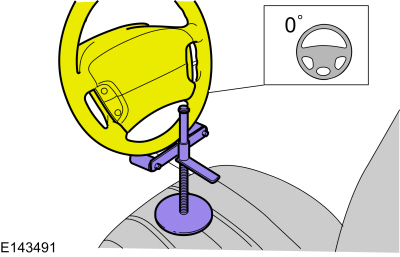
NOTE:
Use a steering wheel holding device (such as Hunter® 28-75-1 or equivalent).
-
NOTICE:
Do not allow the intermediate shaft to rotate while it is disconnected from the gear or damage to the clockspring can occur.
If there is evidence that the intermediate shaft has rotated, the clockspring must be removed and recentered. Refer to Section
501-20B.
-
Refer to:
Cooling System Draining and Vacuum Filling
(303-03A Engine Cooling - 3.7L Duratec (227kW/301PS), General Procedures).
-
Remove the LH and RH front wheels and tires.
Refer to:
Wheel and Tire
(204-04B Wheels and Tires, Removal and Installation).
-
If equipped.
-
-
Remove the following items:
-
Refer to:
Accessory Drive Belt
(303-05A Accessory Drive - 3.7L Duratec (227kW/301PS), Removal and Installation).
-
Refer to:
Air Cleaner Outlet Pipe
(303-12A Intake Air Distribution and Filtering - 3.7L Duratec (227kW/301PS), Removal and Installation).
Refer to:
Air Cleaner
(303-12A Intake Air Distribution and Filtering - 3.7L Duratec (227kW/301PS), Removal and Installation).
-
Refer to:
Battery Tray
(414-01 Battery, Mounting and Cables, Removal and Installation).
-
-
-
-
-
-
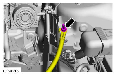
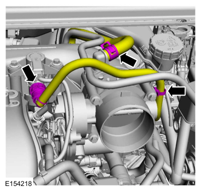
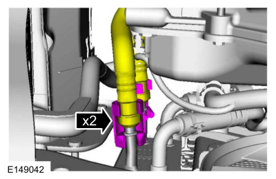
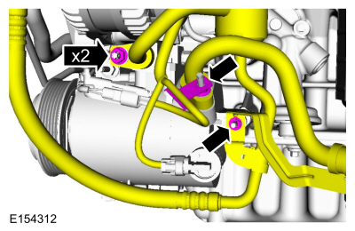
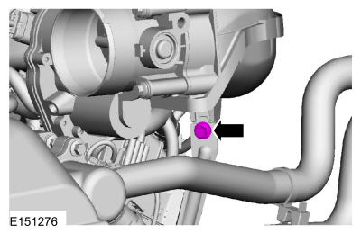
Refer to:
Quick Release Coupling
(310-00B Fuel System - General Information - 3.7L Duratec (227kW/301PS), General Procedures).
General Equipment
: Hose Clamp Remover/Installer
-
-
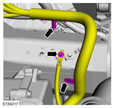
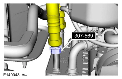
Refer to:
Quick Release Coupling
(310-00B Fuel System - General Information - 3.7L Duratec (227kW/301PS), General Procedures).
-
General Equipment
: Hose Clamp Remover/Installer
-
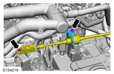
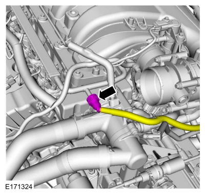
-
Special Tool(s)
: 307-569 Disconnect Tool TOC Line (1/2)
-
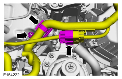
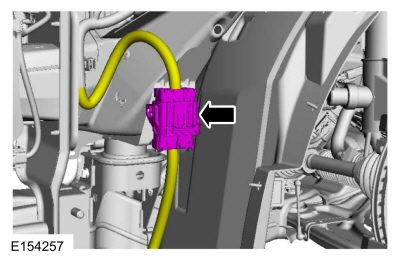
Refer to:
Degas Bottle
(303-03A Engine Cooling - 3.7L Duratec (227kW/301PS), Removal and Installation).
-
-
-
-
-
-
-
-
-
-
-
Refer to:
Brake Disc
(206-03 Front Disc Brake, Removal and Installation).
-
-
-
Refer to:
Exhaust Y-Pipe
(309-00B Exhaust System - 3.7L Duratec (227kW/301PS), Removal and Installation).
-
Torque
:
27 Nm
-
-
-
-
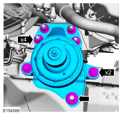
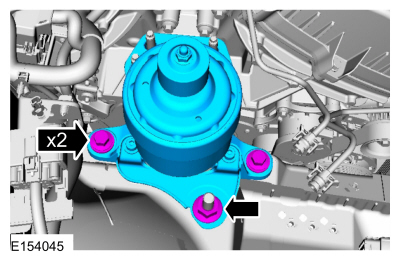
All vehicles
-
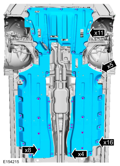
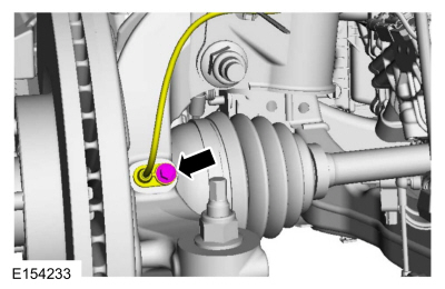
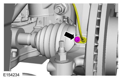
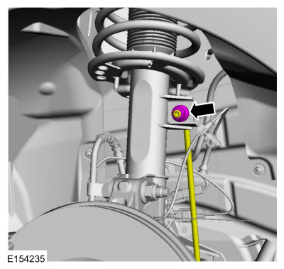
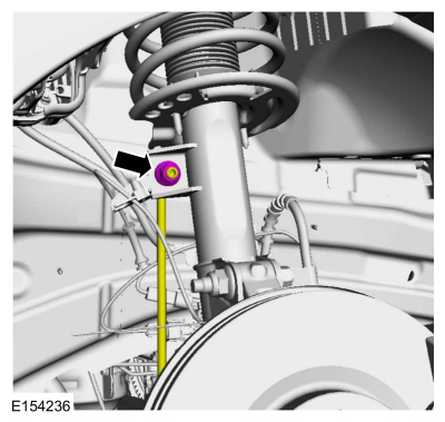
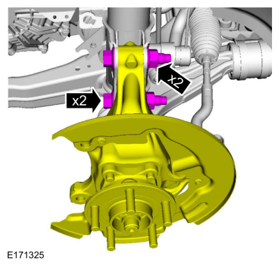
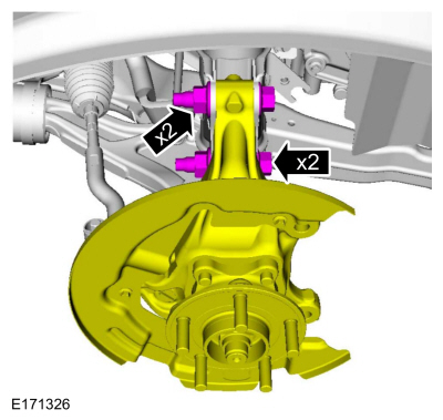
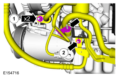
NOTE:
side shown,
side similar.
Both sides.
-
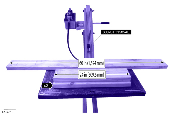
Using a 2 x 6 board, 60 in (1,524 mm) and two 2 x 6 boards 24 in (609.6 mm), position powertrain lift with the 60 in (1,524
mm) board under the 2 control arms and the two 24 in (609.6 mm) boards under the transmission and oil pan.
Install Special Service Tool
: 300-OTC1585AE Powertrain Lift
-
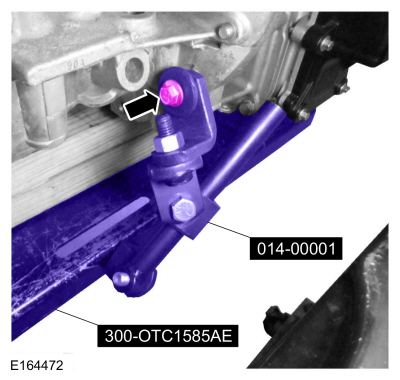
Install the Adjustable Mounting Arm from the powertrain lift table to the LH engine-to-transmission bolt hole.
General Equipment
: Adjustable Mounting Arm
-
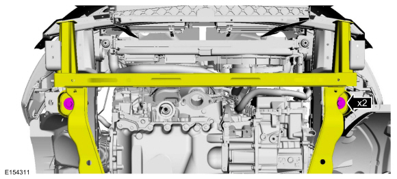
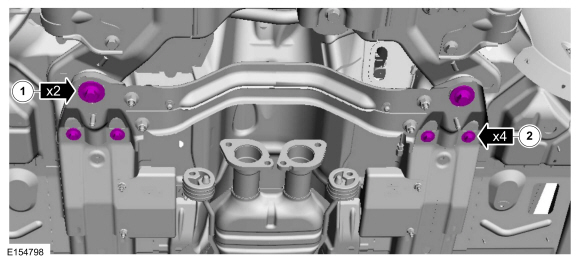
Install a ratchet strap from the front of the subframe under the powertrain lift table to the rear of the subframe, to secure
the subframe to the powertrain lift table.
-
-
-
-
-
-
-
Using the powertrain lift table, lower the subframe and powertrain assembly from the vehicle.
-
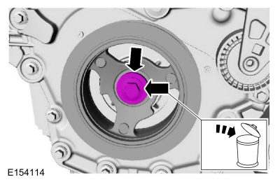
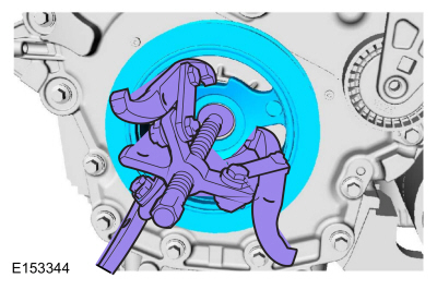
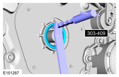
-
General Equipment
: Puller
-
Special Tool(s)
: 303-409 (T92C-6700-CH) Remover, Crankshaft Seal
-
-
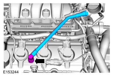
Refer to:
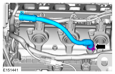
Quick Release Coupling
(310-00B Fuel System - General Information - 3.7L Duratec (227kW/301PS), General Procedures).
-
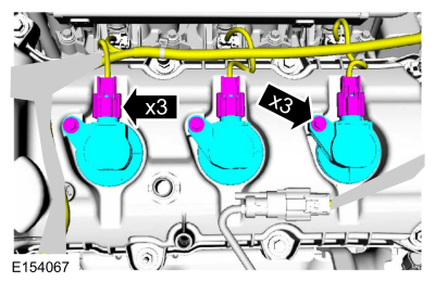
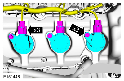
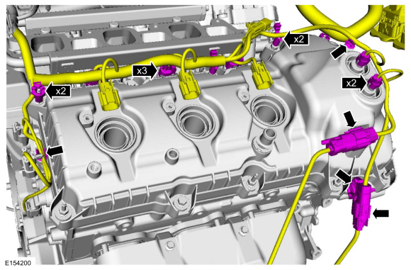
NOTE:
When removing the ignition coil-on-plugs, a slight twisting motion will break the seal and ease removal.
-
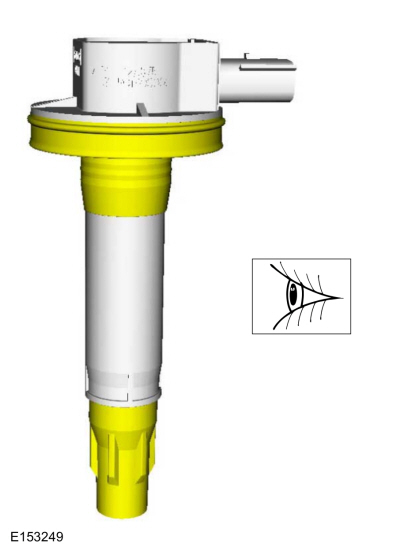
NOTE:
Inspect the coil seals for rips, nicks or tears.
-
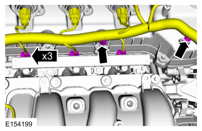
-
-
-
-
Remove.
-
Remove.
-
Loosen.
-
Position aside.
-
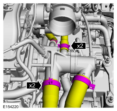
-
-
-
General Equipment
: Hose Clamp Remover/Installer
-
-
-
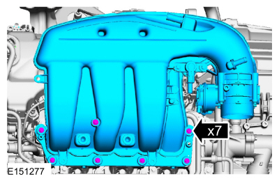
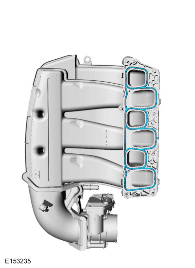
NOTICE:
If the engine is repaired or replaced because of upper engine failure, typically including valve or piston damage, check the
intake manifold for metal debris. If metal debris is found, install a new intake manifold. Failure to follow these instructions
can result in engine damage.
-
-
NOTE:
When removing the ignition coil-on-plugs, a slight twisting motion will break the seal and ease removal.
-
NOTE:
Inspect the coil seals for rips, nicks or tears.
-
General Equipment
: Hose Clamp Remover/Installer
-
-
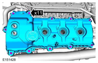
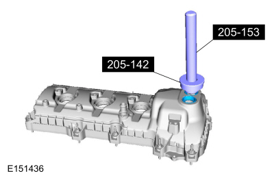
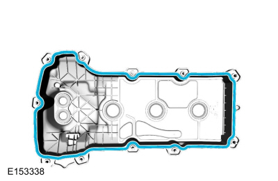
NOTICE:
While removing the valve cover do not apply excessive force to the
oil control solenoid or damage may occur.
NOTICE:
If the
oil control solenoid sticks to the
seal, carefully wiggle the valve cover until the bond breaks free or damage to the
seal and
oil control solenoid may occur.
-
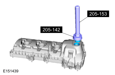
-
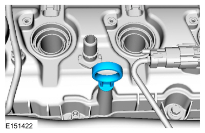
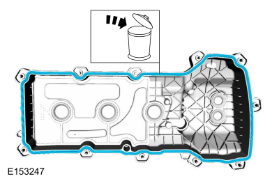
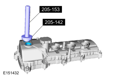
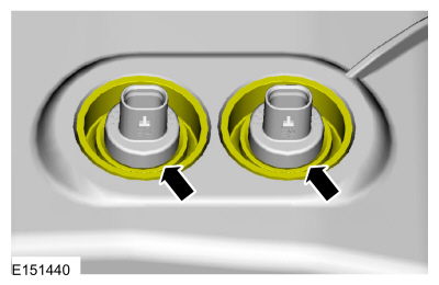
NOTE:
Inspect the
solenoid seals. Remove any damaged seals.
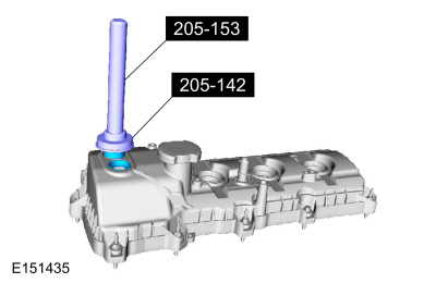
Special Tool(s)
: 205-142 (T80T-4000-J) Installer, Differential Bearing Cone
, 205-153 (T80T-4000-W) Handle
-
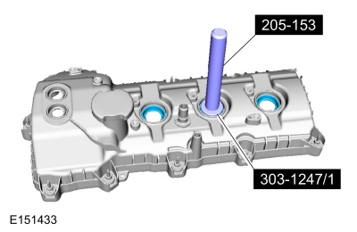
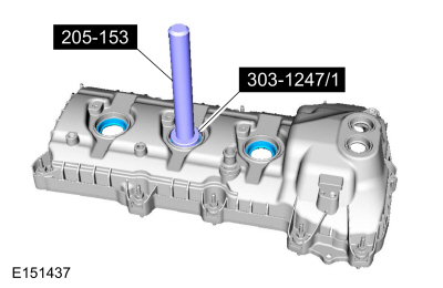
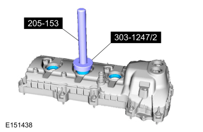
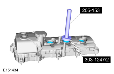
NOTE:
Inspect the spark plug tube seals. Remove any damaged seals.
Special Tool(s)
: 205-153 (T80T-4000-W) Handle
, 303-1247 VCT Spark Plug Tube Seal Remover and Installer
-
NOTICE:
While removing the valve cover do not apply excessive force to the
oil control solenoid or damage may occur.
NOTICE:
If the
oil control solenoid sticks to the
seal, carefully wiggle the valve cover until the bond breaks free or damage to the
seal and
oil control solenoid may occur.
-
-
NOTE:
Inspect the
solenoid seals. Remove any damaged seals.
Special Tool(s)
: 205-142 (T80T-4000-J) Installer, Differential Bearing Cone
, 205-153 (T80T-4000-W) Handle
-
NOTE:
Inspect the spark plug tube seals. Remove any damaged seals.
Special Tool(s)
: 205-153 (T80T-4000-W) Handle
, 303-1247 VCT Spark Plug Tube Seal Remover and Installer
-
-
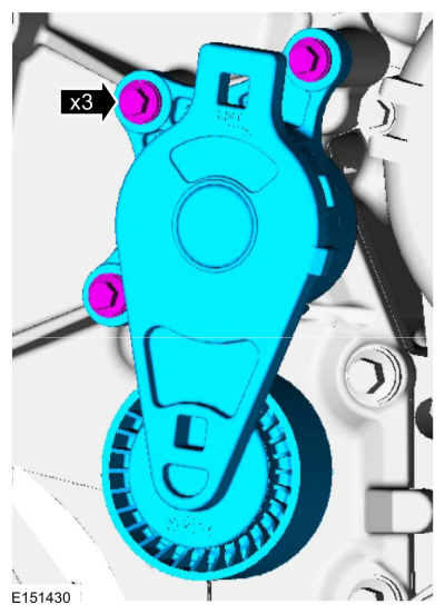
Pry pads.
Installation
All vehicles
-
NOTICE:
Only use a 3M™ Roloc® Bristle Disk (2-in white, part number 07528) to clean the engine front cover. Do not use metal scrapers,
wire brushes or any other power abrasive disk to clean front cover.
-
Clean the engine front cover using a 3M™ Roloc® Bristle Disk (2-in white, part number 07528) in a suitable tool turning at
the recommended speed of 15,000 rpm.
-
Thoroughly wash the engine front cover to remove any foreign material, including any abrasive particles created during the
cleaning process.
-
NOTICE:
Place clean, lint-free shop towels over exposed engine cavities. Carefully remove the towels so foreign material is not dropped
into the engine. Any foreign material (including any material created while cleaning gasket surfaces) that enters the oil
passages or the oil pan, may cause engine failure.
NOTICE:
Do not use wire brushes, power abrasive discs or 3M™ Roloc® Bristle Disk (2-in white part number 07528) to clean the sealing
surfaces. These tools cause scratches and gouges that make leak paths. They also cause contamination that will cause premature
engine failure. Remove all traces of the gasket.
Make sure that the mating faces of the engine block are clean and free of foreign material.
Material
: Motorcraft® Silicone Gasket Remover
/ ZC-30
Material
: Motorcraft® Metal Surface Prep
/ ZC-31-A
-
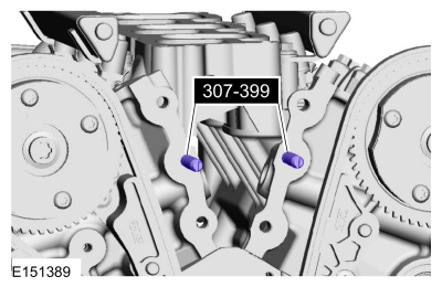
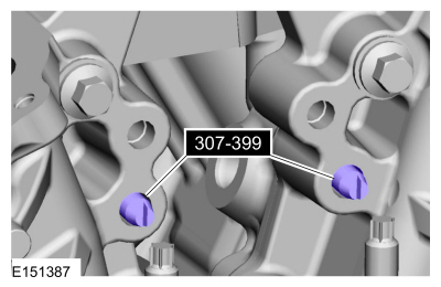
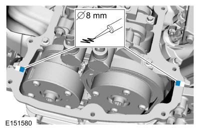
Install Special Service Tool
: 307-399 Alignment Pins, Transmission Fluid Pump
-
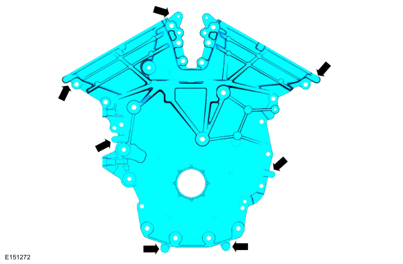
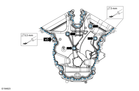
NOTICE:
Failure to use Motorcraft® High Performance Engine RTV Silicone may cause the engine oil to foam excessively and result in
serious engine damage.
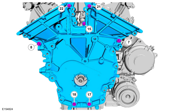
NOTE:
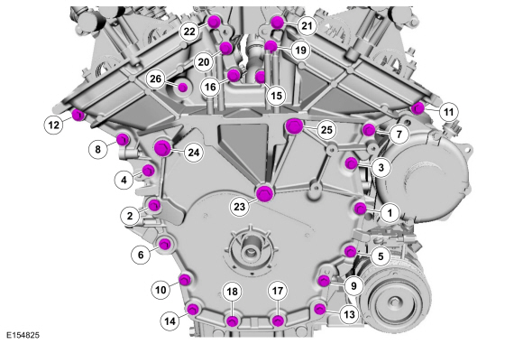
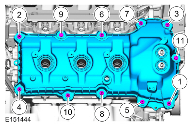
The engine front cover and bolts 7, 8, 15, 17, 18, 21 and 22 must be installed within 4 minutes of the initial sealant application.
The remainder of the engine front cover bolts must be installed and tightened within 35 minutes of the initial sealant application.
If the time limits are exceeded, the sealant must be removed, the sealing area cleaned and sealant reapplied. To clean the
sealing area, use silicone gasket remover and metal surface prep. Failure to follow this procedure can cause future oil leakage.
Material
: Motorcraft® High Performance Engine RTV Silicone
/ TA-357
(WSE-M4G323-A6)
-
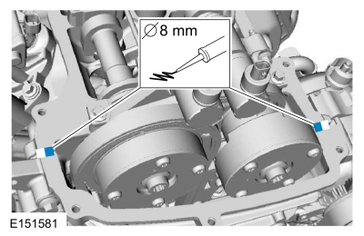
NOTE:
Make sure the 2 locating dowel pins are seated correctly in the cylinder block.
Torque
:
3 Nm
-
Remove Special Service Tool
: 307-399 Alignment Pins, Transmission Fluid Pump
-
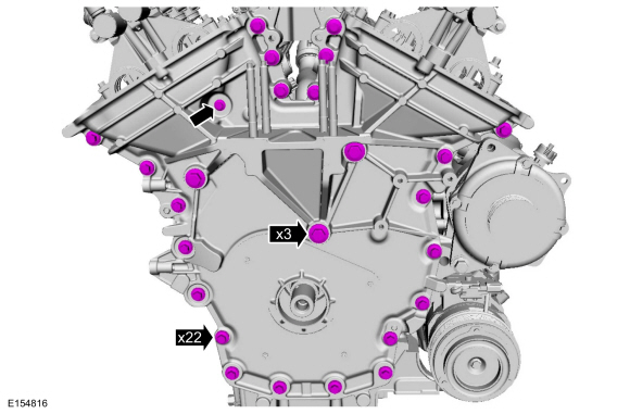
Torque
:
Stage 1:
Tighten bolts 1 thru 22 to 10 Nm
Stage 2:
Tighten bolts 23, 24 and 25 to 15 Nm
Stage 3:
Tighten bolt 26 to 10 Nm
Stage 4:
Loosen bolt 26 one turn(s)
Stage 5:
Tighten bolts 23, 24 and 25 to 30 Nm (22 lb-ft) plus an additional 90°
Stage 6:
Tighten bolts 1 thru 22 to 20 Nm (177 lb-in) plus an additional 45°
Stage 7:
Tighten bolt 26 to 10 Nm (89 lb-in) plus an additional 45 °
-
NOTE:
Installation of new seals is only required if damaged seals were removed.
Special Tool(s)
: 303-1247 VCT Spark Plug Tube Seal Remover and Installer
, 205-153 (T80T-4000-W) Handle
-
NOTE:
Installation of new seals is only required if damaged seals were removed.
Special Tool(s)
: 205-142 (T80T-4000-J) Installer, Differential Bearing Cone
, 205-153 (T80T-4000-W) Handle
-
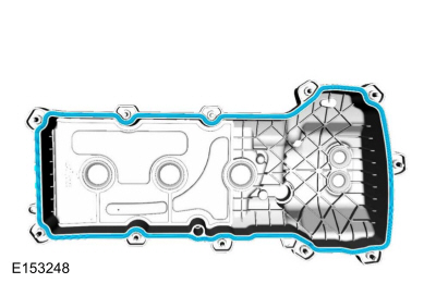
NOTE:
If the valve cover is not installed and the fasteners tightened within 4 minutes, the sealant must be removed and the sealing
area cleaned. To clean the sealing area, use silicone gasket remover and metal surface prep. Failure to follow this procedure
can cause future oil leakage.
Material
: Motorcraft® Metal Surface Prep
/ ZC-31-A
Material
: Motorcraft® Silicone Gasket Remover
/ ZC-30
Material
: Motorcraft® High Performance Engine RTV Silicone
/ TA-357
(WSE-M4G323-A6)
-
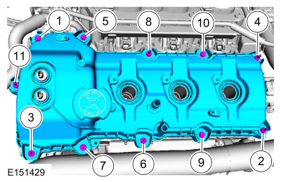
-
Torque
:
10 Nm
-
Make sure the
seals in the valve cover are below the top of the
oil control solenoid electrical connector or the
seal may leak oil.
-
NOTE:
Installation of new seals is only required if damaged seals were removed.
Special Tool(s)
: 303-1247 VCT Spark Plug Tube Seal Remover and Installer
, 205-153 (T80T-4000-W) Handle
-
NOTE:
Installation of new seals is only required if damaged seals were removed.
Special Tool(s)
: 205-142 (T80T-4000-J) Installer, Differential Bearing Cone
, 205-153 (T80T-4000-W) Handle
-
NOTE:
If the valve cover is not installed and the fasteners tightened within 4 minutes, the sealant must be removed and the sealing
area cleaned. To clean the sealing area, use silicone gasket remover and metal surface prep. Failure to follow this procedure
can cause future oil leakage.
Material
: Motorcraft® Metal Surface Prep
/ ZC-31-A
Material
: Motorcraft® Silicone Gasket Remover
/ ZC-30
Material
: Motorcraft® High Performance Engine RTV Silicone
/ TA-357
(WSE-M4G323-A6)
-
-
Torque
:
10 Nm
-
Make sure the
seals in the valve cover are below the top of the
oil control solenoid electrical connector or the
seal may leak oil.
-
-
General Equipment
: Hose Clamp Remover/Installer
-
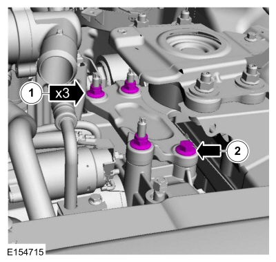
NOTE:
Apply a small amount of dielectric grease to the inside of the ignition coil-on-plug boots before attaching to the spark plugs.
Material
: Silicone Brake Caliper Grease and Dielectric Compound
/ XG-3-A
(ESE-M1C171-A)
Torque
:
7 Nm
NOTICE:
If the engine is repaired or replaced because of upper engine failure, typically including valve or piston damage, check the
intake manifold for metal debris. If metal debris is found, install a new intake manifold. Failure to follow these instructions
can result in engine damage.
-
-
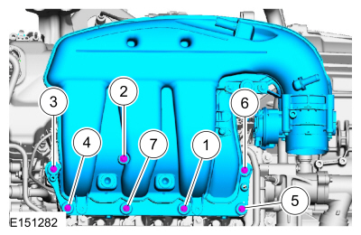
Torque
:
Stage 1:
10 Nm
Stage 2:
45°
-
Torque
:
10 Nm
-
-
General Equipment
: Hose Clamp Remover/Installer
-
-
-
-
-
Position.
-
Install.
Torque
:
8 Nm
-
Install.
Torque
:
47 Nm
-
Tighten.
Torque
:
47 Nm
-
Torque
:
17 Nm
-
-
-
NOTE:
Apply a small amount of dielectric grease to the inside of the ignition coil-on-plug boots before attaching to the spark plugs.
Material
: Silicone Brake Caliper Grease and Dielectric Compound
/ XG-3-A
(ESE-M1C171-A)
Torque
:
7 Nm
-
Refer to:
Quick Release Coupling
(310-00B Fuel System - General Information - 3.7L Duratec (227kW/301PS), General Procedures).
-
Torque
:
11 Nm
-
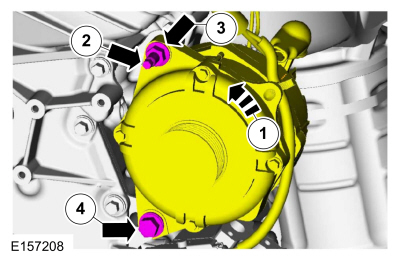
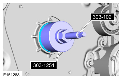
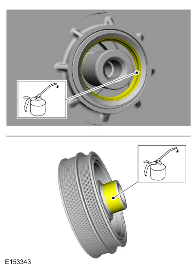
NOTE:
Apply clean engine oil to the crankshaft front seal bore in the engine front cover.
Special Tool(s)
: 303-102 Installer, Crankshaft Pulley
, 303-1251 Installer, Front Seal
Material
: Motorcraft® SAE 5W-20 Premium Synthetic Blend Motor Oil
/ XO-5W20-QSP
(WSS-M2C945-A)
-
Material
: Motorcraft® SAE 5W-20 Premium Synthetic Blend Motor Oil
/ XO-5W20-QSP
(WSS-M2C945-A)
-
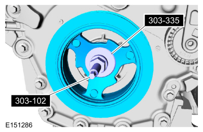
Special Tool(s)
: 303-102 Installer, Crankshaft Pulley
, 303-335 (T88T-6701-A) Installer, Front Cover Oil Seal
-
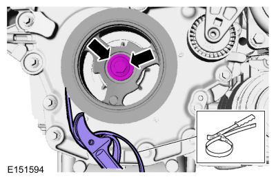
General Equipment
: Strap Wrench
Torque
:
Stage 1:
120 Nm
Stage 2:
Loosen 1 turn(s)
Stage 3:
50 Nm
Stage 4:
90°
-
Using the powertrain lift table, raise the subframe and powertrain assembly into the vehicle.
-
-
Torque
:
63 Nm
-
Torque
:
80 Nm
-
Torque
:
90 Nm
-
Torque
:
63 Nm
-
NOTE:
Align the marks made in removal.
Finger tight at this stage.
-
NOTE:
Align the marks made in removal.
Finger tight at this stage.
-
NOTE:
While tightening the subframe bolts, make sure the front subframe does not move.
Torque
:
235 Nm
-
-
Torque
:
Stage 1:
103 Nm
Stage 2:
270°
-
Torque
:
60 Nm
-
Torque
:
235 Nm
-
Torque
:
235 Nm
-
Remove the ratchet strap from the front of the subframe to the rear of the subframe.
-
Remove Special Service Tool
: 300-OTC1585AE Powertrain Lift
General Equipment
: Adjustable Mounting Arm
-
Torque
:
70 Nm
All vehicles
-
-
-
Torque
:
20 Nm
-
Torque
:
15 Nm
-
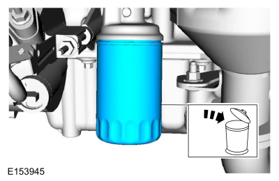
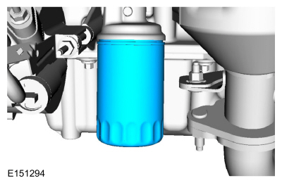
NOTE:
Do not lubricate the engine oil filter seal.
Torque
:
Stage 1:
5 Nm
Stage 2:
180°
-
Refer to:
Exhaust Y-Pipe
(309-00B Exhaust System - 3.7L Duratec (227kW/301PS), Removal and Installation).
-
-
Torque
:
24 Nm
-
Refer to:
Brake Disc
(206-03 Front Disc Brake, Removal and Installation).
-
Torque
:
150 Nm
-
Torque
:
150 Nm
-
Torque
:
9 Nm
-
Torque
:
9 Nm
-
Torque
:
15 Nm
-
Torque
:
15 Nm
-
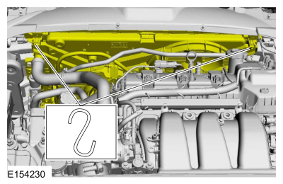
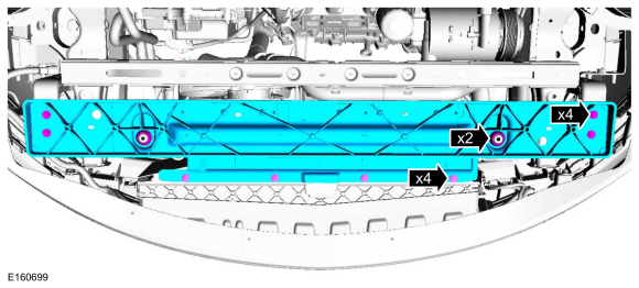
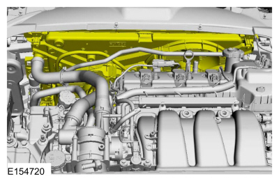
Remove the cooling module support.
-
Torque
:
10 Nm
-
-
-
Refer to:
Degas Bottle
(303-03A Engine Cooling - 3.7L Duratec (227kW/301PS), Removal and Installation).
-
-
-
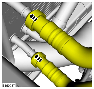
General Equipment
: Hose Clamp Remover/Installer
-
Refer to:
Quick Release Coupling
(310-00B Fuel System - General Information - 3.7L Duratec (227kW/301PS), General Procedures).
-
Torque
:
7 Nm
-
Refer to:
Quick Release Coupling
(310-00B Fuel System - General Information - 3.7L Duratec (227kW/301PS), General Procedures).
General Equipment
: Hose Clamp Remover/Installer
-
Torque
:
12 Nm
-
Torque
:
12 Nm
-
-
-
Torque
:
12 Nm
-
Install the following items:
-
Refer to:
Battery Tray
(414-01 Battery, Mounting and Cables, Removal and Installation).
-
Refer to:
Air Cleaner
(303-12A Intake Air Distribution and Filtering - 3.7L Duratec (227kW/301PS), Removal and Installation).
-
Refer to:
Accessory Drive Belt
(303-05A Accessory Drive - 3.7L Duratec (227kW/301PS), Removal and Installation).
-
-
If equipped.
-
Install the LH and RH front wheels and tires.
Refer to:
Wheel and Tire
(204-04B Wheels and Tires, Removal and Installation).
-
NOTICE:
Do not allow the intermediate shaft to rotate while it is connecting the gear or damage to the clockspring can occur. If there
is evidence that the intermediate shaft has rotated, the clockspring must be removed and recentered. Refer to Section 501-20B.
Torque
:
25 Nm
-
Fill the engine with clean engine oil.
Refer to:
Specifications
(303-01A Engine - 3.7L Duratec (227kW/301PS), Specifications).
Material
: Motorcraft® SAE 5W-20 Premium Synthetic Blend Motor Oil
/ XO-5W20-QSP
(WSS-M2C945-A)
-
Refer to:
Cooling System Draining and Vacuum Filling
(303-03A Engine Cooling - 3.7L Duratec (227kW/301PS), General Procedures).
-
Refer to:
Air Conditioning (A/C) System Recovery, Evacuation and Charging
(412-00 Climate Control System - General Information, General Procedures).
-
Refer to:
Selector Lever Cable Adjustment
(307-05A Automatic Transmission External Controls - Vehicles With: 6-Speed Automatic Transmission - 6F50, General Procedures).
-
After completing the repairs, perform the Misfire Monitor Neutral Profile Correction procedure.
Copyright © Ford Motor Company